Lascia un messaggio
Se sei interessato ai nostri prodotti e desideri maggiori dettagli, lascia un messaggio qui, ti risponderemo il prima possibile.

Water pressure is the driving force behind every firefighting operation. Without adequate pressure, water cannot reach the fire, penetrate burning materials, or be effective. Fire fighting trucks must not only generate pressure but also maintain it consistently throughout the entire firefighting operation.
This article explains how fire trucks produce, control, and sustain water pressure, covering the key components and principles involved.

Water pressure in a fire truck comes from the fire pump. The pump is driven by the truck's engine through a power take-off (PTO) system. When the PTO is engaged, engine power is redirected to spin the pump impeller at high speed.
The impeller is a rotating disc with curved vanes. As it spins, it throws water outward by centrifugal force. This action creates two effects simultaneously:
Low pressure at the center (eye of the impeller): Water is drawn in from the tank or intake hose
High pressure at the outer edge: Water is forced out into the discharge piping
This is why most fire truck pumps are called centrifugal pumps.

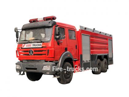
Pump size and power must match the vehicle's intended use. Large fire trucks, such as a 25,000-liter water/foam combination truck, require more powerful pumps to maintain high pressure while delivering large volumes of water. These heavy-duty pumps are designed for efficiency and reliability, even under extreme conditions.
For smaller trucks, such as a 3,000-liter light foam pumper, a less powerful but still effective pump is used. These trucks do not need to deliver as much water, and the smaller pump is sufficient to maintain the pressure required for their operations.
Additionally, the height of the onboard water tank and the position of the pump affect pressure. Water flows by gravity from the tank to the pump, but the pump must still increase the pressure to push water effectively through the hoses.
Once pressure is generated, it must be controlled to match the specific firefighting task. Different situations require different pressures.
The simplest way to adjust pressure is by changing engine speed. Increasing engine RPM spins the pump impeller faster, which increases pressure. Decreasing RPM lowers pressure. The pump operator controls engine speed from the pump panel using an electronic throttle.

Modern fire trucks are equipped with electronic pressure governors. These devices automatically maintain the set pressure regardless of changes in flow.
When a firefighter opens or closes a nozzle, the flow demand changes. Without a governor, pressure would drop when a new hose line is opened or spike when a line is closed. The governor senses these changes and automatically adjusts engine speed to keep pressure constant.
| Mode | Function |
|---|---|
| Pressure mode | Maintains a preset pressure regardless of flow changes |
| RPM mode | Maintains a preset engine speed (used for foam operations or when a specific flow is needed) |
As a backup to electronic governors, mechanical relief valves provide additional safety. If pressure exceeds a set limit, the relief valve opens, bypassing excess water back to the tank or to the suction side of the pump. This prevents hose bursts and pump damage.
Water loses pressure as it flows through hoses due to friction loss. The longer the hose, the greater the loss. Fire trucks compensate for this in several ways.
The pump operator calculates the pressure needed at the nozzle and adds the pressure that will be lost in the hose. For example, if the nozzle requires 100 psi and the hose will lose 50 psi over its length, the operator sets the pump to deliver 150 psi.

Friction loss decreases significantly as hose diameter increases. Larger diameter hoses have less internal resistance, allowing water to flow more freely and maintain pressure. A 2.5-inch hose has much less friction loss than a 1.75-inch hose at the same flow rate. For long supply lines, fire trucks use large diameter hoses (LDH) of 4 or 5 inches to minimize pressure loss.
For extremely long distances, multiple fire trucks can work in series. The first truck pumps water to the second truck, which boosts pressure and sends it further. This is called relay pumping.
If the pump cannot draw enough water, pressure will drop regardless of engine speed. Common causes include:
Clogged intake strainer
Collapsed suction hose (soft hose used for drafting)
Air leaks in the intake line
Prevention: Use rigid suction hose for drafting. Check and clean strainers regularly. Ensure all intake connections are tight.
Cavitation occurs when the pump does not receive enough water. Instead of water, the impeller spins in a mixture of water and vapor bubbles. When these bubbles collapse, they create shock waves that damage the impeller and cause severe pressure fluctuation.
Signs of cavitation: Loud rattling noise from the pump, erratic pressure gauge readings, reduced flow.
Prevention: Never run the pump faster than the water supply can deliver. Monitor intake pressure gauges. If vacuum is too high, reduce pump speed or check for intake restrictions.
Every pump has a maximum flow and pressure rating. Operating beyond these limits will cause pressure to drop. The pump operator must know the pump's performance curve and stay within safe operating ranges.
Foam systems add complexity to pressure maintenance.
A foam fire truck has two separate tanks: one for water and one for foam concentrate. The pump must draw from both tanks and mix them at a precise ratio before discharge.

The Role of the Foam Proportioner
The foam proportioner is the key component that controls the mixing ratio.
It is installed in the pipeline. As water flows through, it creates a vacuum that draws foam concentrate into the water stream. Common mixing ratios are 1%, 3%, and 6%.
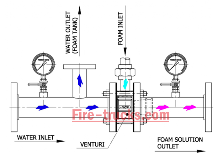
The proportioner is highly sensitive to inlet water pressure.
| Condition | Result |
|---|---|
| Pressure too low | Weak vacuum → insufficient foam intake |
| Pressure too high | Incorrect ratio → waste of concentrate or poor foam quality |
Additional Hardware
Some foam trucks include a cooling water line with a control valve. This cools the power take-off (PTO) during prolonged foam operations, ensuring the drive system runs reliably for extended periods.
If pressure drops during firefighting, take these steps:
Increase engine speed – Throttle up to raise pump RPM
Close unnecessary outlets – More pressure goes to remaining hoses
Check water supply – Is the strainer clogged? Is the water source adequate?
Switch to governor mode – Let automatic control take over
If pressure still cannot be restored, the nozzle firefighter may need to move closer or use a smaller nozzle to reduce flow demand.
| Component | Function |
|---|---|
| Pressure gauges | Display pump discharge pressure and intake pressure (vacuum) |
| Electronic pressure governor | Automatically maintains set pressure |
| Relief valve | Prevents over-pressurization |
| Flow meter | Measures water flow rate (used to verify pump output) |
| Intake pressure gauge | Shows vacuum (drafting) or positive pressure (hydrant supply) |
The piping system carries water from the tank or external source to the pump and then to the discharge outlets. All pipelines are made of seamless steel pipe, connected by flanges to various components. Seamless steel pipe offers high pressure resistance, good corrosion resistance, and excellent sealing properties.

Typical configuration example (based on a CS TRUCKS fire truck model):
| Pipeline Type | Size | Quantity | Control Valve |
|---|---|---|---|
| Tank discharge line | DN150 | 1 line | Manual butterfly valve |
| External intake port | DN150 | 1 port | Manual butterfly valve |
| Standard discharge outlets | DN80 and DN65 | 2 (one each side) | Pump panel controlled |
| Fire monitor line | DN80 | 1 line | Monitor ball valve |
| External fill lines | DN65 | 2 lines | Pump panel controlled |
| Internal fill line | DN65 | 1 line | Pump panel controlled |
| Drain line | - | 1 line | Drain valve |
Flexible couplings are used at critical connections, such as between the tank and the pump, to absorb vibrations from vehicle movement and pump operation. A drain valve is installed at the lowest point of the piping system to drain residual water after operations, preventing freezing and corrosion. Additionally, a cooling water line with a ball valve is provided to cool the PTO during complex operating conditions.
Fire trucks maintain water pressure through a combination of centrifugal pumps, electronic governors, relief valves, properly sized hoses, and skilled pump operators.
The centrifugal pump generates pressure by spinning an impeller. Larger trucks require more powerful pumps, while smaller trucks use appropriately sized pumps for their needs.
The pressure governor automatically maintains the set pressure
Relief valves provide mechanical backup against over-pressure
Larger hoses and relay pumping minimize pressure loss over long distances
Foam systems require precise calibration of the proportioner to maintain both mixture ratio and pressure
The pump operator monitors and adjusts pressure throughout the operation
Without consistent pressure, water cannot reach the fire or do its job effectively. Maintaining water pressure is not automatic — it requires proper equipment, correct setup, regular maintenance, and constant attention from trained personnel.
Whether preparing a large fire truck for a major city fire department or a smaller truck for rural areas, every factor related to water pressure must be considered. You need a fire truck that delivers reliable and steady pressure when it matters most.


Potresti essere interessato alle seguenti informazioni
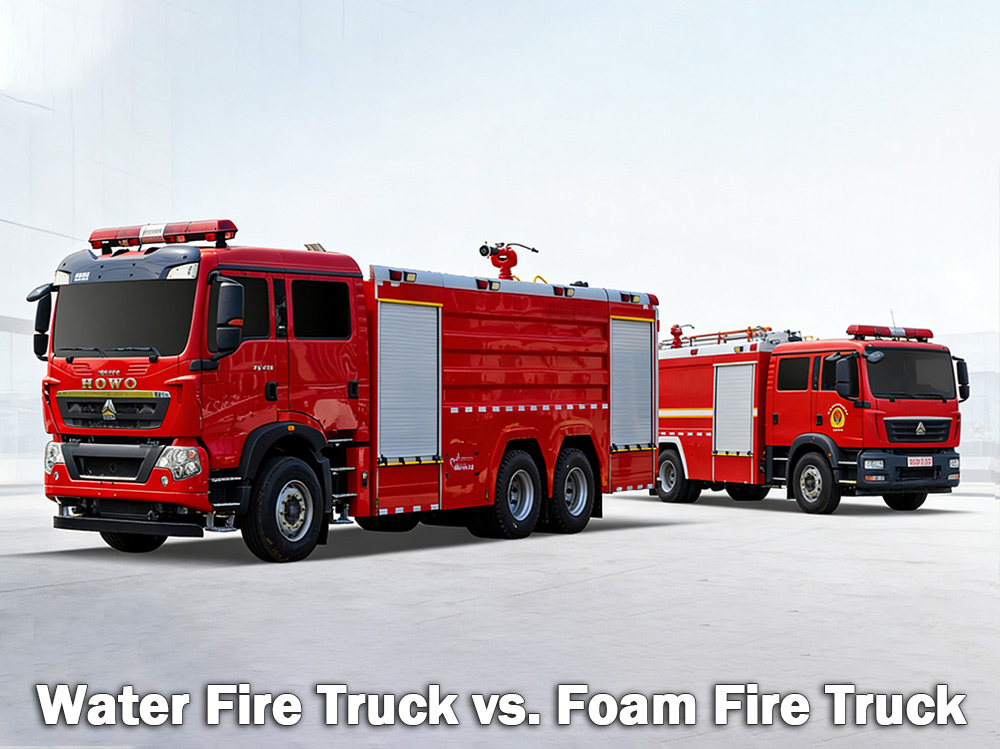
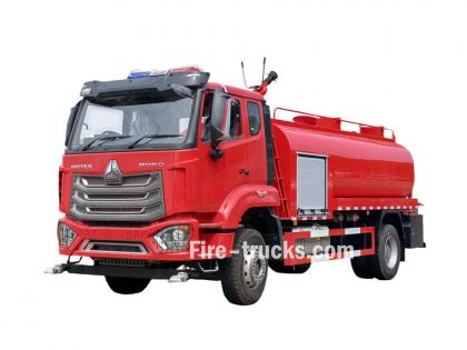
Autobotti antincendio I camion dei pompieri con sistema a schiuma sono adatti a spegnere incendi ordinari che coinvolgono legno, carta e stoffa. I camion dei pompieri con sistema a schiuma sono adatti a spegnere incendi di liquidi infiammabili come benzina e olio. La scelta del mezzo più adatto dipende dai rischi presenti. UN autopompa antincendio Trasporta un grande serbatoio d'acqua e si affida a una pompa ad alta pressione per erogare l'acqua tramite tubi flessibili o un cannone ad acqua. È il tipo di autopompa più comune utilizzato dai vigili del fuoco municipali e dai siti industriali di tutto il mondo. UN camion dei pompieri con schiuma D'altra parte, è specificamente progettato per trasportare e distribuire schiuma antincendio. Quando l'acqua da sola non è in grado di estinguere efficacemente un incendio, come nel caso di liquidi infiammabili, sostanze chimiche o incendi di carburante, la schiuma è la scelta migliore. La schiuma agisce creando una sorta di "coperta" sopra il fuoco, interrompendo l'apporto di ossigeno e impedendo la riaccensione. I. Cos'è un'autopompa antincendio? Un'autopompa antincendio è esattamente ciò che il nome suggerisce: un veicolo dotato di un grande serbatoio d'acqua, una potente pompa e tubi o lance per erogare acqua sugli incendi. Il serbatoio d'acqua ha in genere una capacità compresa tra 500 e 3.000 galloni (circa 2.000-12.000 litri). La pompa aspira l'acqua dal serbatoio o da una fonte esterna come un idrante, un lago o uno stagno, e la spinge attraverso i tubi ad alta pressione. Dove le autobotti antincendio sono più efficaci: I camion dei pompieri sono ideali per Incendi di classe A che coinvolgono combustibili ordinari: Legno e legname Carta e cartone Tessuto e stoffa Gomma e plastica Erba, arbusti e materiali forestali Se l'incendio coinvolge materiali combustibili in una casa, un magazzino o un campo, di solito l'acqua è sufficiente a spegnerlo. Limitazioni dell'acqua: L'acqua ha un grosso punto debole. Quando viene spruzzata su liquidi infiammabili come benzina, olio o sostanze chimiche, affonda perché è più pesante di questi combustibili. Il combustibile galleggia in superficie e continua a bruciare. In alcuni casi, l'acqua può persino propagare l'incendio a un'area più ampia. Ecco perché l'acqua da sola non è efficace per spegnere gli incendi di liquidi infiammabili. Specifiche della pompa antincendio dell'autopompa antincendio: Autocisterna antincendio addetto antincendio specifiche: II. Cos'è un'autopompa con schiuma? Un'autopompa antincendio a schiuma è un veicolo specializzato progettato per trasportare e distribuire schiuma antincendio. È dotata di due serbatoi separati: uno per l'acqua e uno per il concentrato di schiuma. Un sistema di dosaggio della schiuma miscela i due componenti in un rapporto specifico, in genere dell'1%, 3% o 6% di concentrato di schiuma rispetto all'acqua. Questa miscela passa quindi attraverso un ugello dove viene aggiunta aria, creando una coltre di schiuma espansa e s...
Dettagli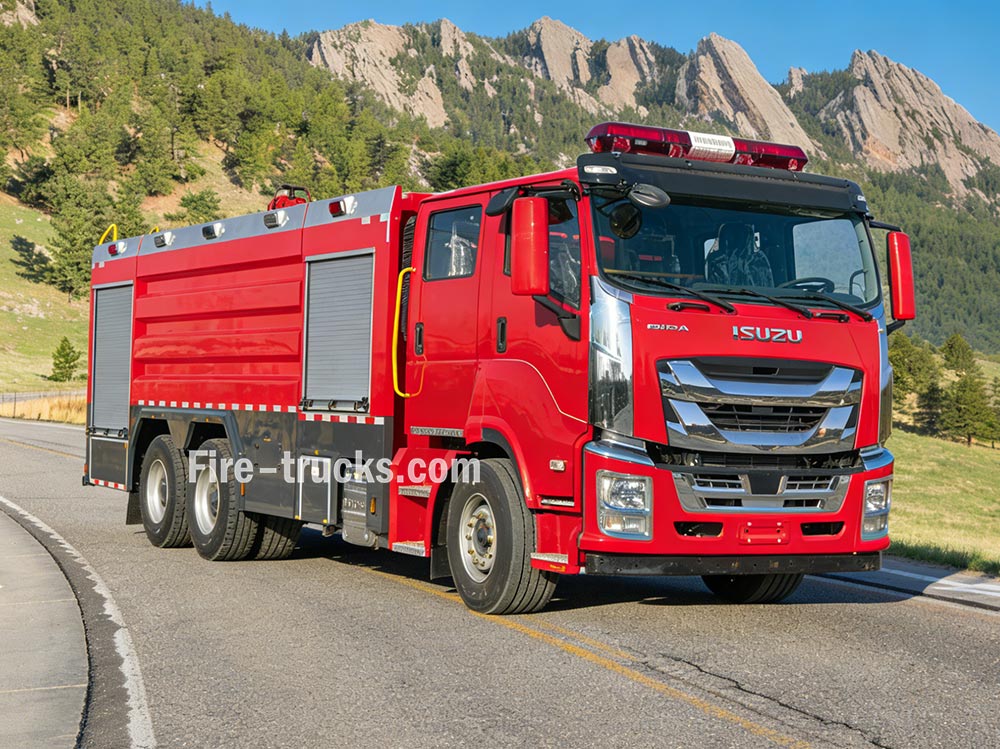
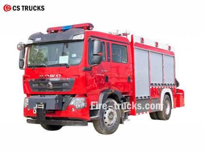
Autopompe Il loro funzionamento si basa sul coordinamento di molteplici sistemi per garantire l'approvvigionamento idrico, la generazione di pressione e lo spegnimento degli incendi. La comprensione di questi principi aiuta le squadre antincendio a operare efficacemente nelle situazioni di emergenza. » I. Come funzionano i camion dei pompieri: ▪ A. Sistema di pompaggio: Il cuore del sistema antincendio: Il cuore di ogni autopompa è la sua pompa. Questa potente unità aspira l'acqua dal serbatoio di bordo o da una fonte esterna, come un idrante, un lago o uno stagno, e la distribuisce attraverso tubi ad alta pressione. La pompa più comunemente utilizzata è la pompa centrifuga, che si basa su una girante rotante per pressurizzare e spostare l'acqua. I vigili del fuoco controllano il flusso d'acqua utilizzando una serie di leve e manometri sul pannello di controllo della pompa. Possono regolare la pressione secondo necessità e dirigere l'acqua verso più manichette contemporaneamente. Tipo di pompa Caratteristiche Migliore applicazione Pompa centrifuga monostadio Flusso elevato, pressione moderata Vigili del fuoco municipali in generale Pompa centrifuga a due stadi Commutabile tra volume e pressione Edifici alti, lunghi tubi flessibili Pompa multistadio pressione molto alta Impianti industriali, sistemi di schiuma ▪ Parametri chiave della pompa: › Portata: da 1.200 a 6.000 litri al minuto (a seconda del modello) › Pressione massima: 1,0 - 2,5 MPa (10-25 bar) › Tempo di innesco: ≤30 secondi ▪ B. Serbatoio e sistema di stoccaggio dell'acqua: › Capacità del serbatoio: da 500 a 1.500 galloni (circa da 2.000 a 6.000 litri), a seconda delle dimensioni e del tipo di veicolo › Materiale del serbatoio: acciaio inossidabile resistente alla corrosione o acciaio al carbonio rivestito › Deflettori interni: Scomparti multipli con design anti-sovrapressione per controllare il movimento dell'acqua durante gli interventi di emergenza › Tempo di riempimento: ≤3 minuti tramite idrante antincendio o aspirazione › Indicatore del livello dell'acqua: indicatore visivo sul lato del serbatoio; display opzionale in cabina Il serbatoio è costruito con materiali resistenti alla corrosione, in genere acciaio inossidabile o acciaio al carbonio rivestito, con piastre deflettrici interne che controllano l'afflusso d'acqua durante la guida in situazioni di emergenza. ▪ C. Sistemi di tubi flessibili e ugelli I camion dei pompieri trasportano vari tipi di tubi flessibili con funzioni diverse: › Tubo di attacco: diametro da 1,5 a 2,5 pollici — eroga acqua direttamente alla fonte dell'incendio › Tubo di alimentazione: 4 - 5 pollici di diametro — trasporta l'acqua dagli idranti o da altre pompe › Tubo di sovralimentazione: piccolo diametro su avvolgitubo — utilizzato per piccoli incendi come incendi di erba o di veicoli All'estremità del tubo, l'ugello consente ai vigili del fuoco di controllare il getto d'acqua, regolandone la pressione, il modello e la direzione in base al tipo di incen...
Dettagli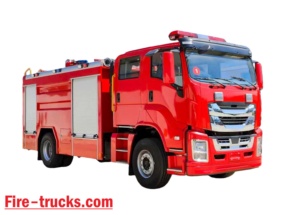
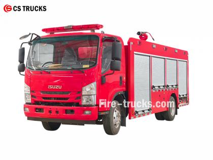
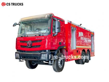
Essendo la fabbrica di autopompe Isuzu più professionale, il progetto principale dell'autopompa antincendio Isuzu NPR con sistema ad acqua e schiuma consiste nell'integrare un sistema antincendio a schiuma in un'autocisterna, creando un'attrezzatura antincendio composita in grado di spruzzare sia acqua che schiuma. Può estinguere autonomamente gli incendi, fornire acqua o miscela di schiuma ad altre attrezzature ed è adatta per operazioni in aree aride e con scarsità d'acqua. ★ Tecnico Specifiche Tutti i camion dei pompieri di CS Trucks, realizzati al 100% in base alle esigenze del cliente. Capacità Modello del motore Acqua Schiuma Pompa antincendio Addetto antincendio 2.500 litri ISUZU 4HK1 / 19 0 CV 2.500 litri 500 litri Pompa antincendio CB10/40 PL8/32 Autocarro con cabina e telaio ISUZU Fire Truck ufficiale del 2026 Disegno originale del telaio dell'autopompa del 2026 Articolo Dettagli di progettazione dei camion dei pompieri Isuzu Nucleo di progettazione Integra un sistema di estinzione a schiuma in un'autocisterna antincendio, creando un veicolo antincendio a doppia capacità in grado di erogare sia acqua che schiuma. Le caratteristiche includono: • Sistema antincendio indipendente • Fornitura di acqua o miscela di schiuma ad altre apparecchiature • Adatto ad aree aride o con scarsità d'acqua, consente un utilizzo multifunzionale Concetto di design generale Progettato per soddisfare le esigenze antincendio in officine e aree circostanti, con capacità potenziate per incendi di olio, di origine elettrica e di materiali solidi, il veicolo è costituito da un telaio e da una carrozzeria specializzata, che privilegia l'affidabilità, la multifunzionalità e la facilità d'uso. Selezione del telaio • Utilizza telai di tipo II di comprovata affidabilità per impieghi medi o pesanti • La trazione integrale è consigliata per migliorare la mobilità e la trazione su terreni complessi NUOVO DESIGN 2026 PER GLI AUTOCARRI ANTINCENDIO ISUZU 700P Componenti principali del sistema e punti chiave della progettazione 1. Serbatoio dell'acqua e serbatoio del liquido schiumogeno • Materiale: acciaio inossidabile, resistente alla corrosione • Capacità consigliata: serbatoio dell'acqua 3000–5000 litri, serbatoio del liquido schiumogeno 300–600 litri • Ottimizzazione strutturale: deflettori interni separano le camere dell'acqua e della schiuma, commutabili tramite porte di collegamento in modalità a serbatoio d'acqua singolo, consentendo un utilizzo multiuso. 2. Sistema di dosaggio della schiuma • Utilizza un dosatore a pressione bilanciata (componente principale) per miscelare con precisione acqua e concentrato di schiuma in rapporti del 3% o del 6%. • Uscita stabile, non influenzata da fluttuazioni di portata o pressione, adatta anche a operatori non specializzati. • Dotato di ingresso esterno per l'aspirazione della schiuma per il rifornimento in loco 3. Sistema di scarico • Pompa antincendio: pompa centrifuga multistadio ad alta efficienza e risparmio energetico, por...
Dettagli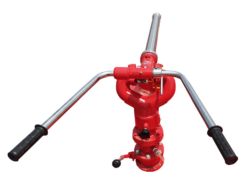
Il PF5-15 monitor fisso di polvere secca Utilizza polvere secca come mezzo e si basa su una base fissa per una spruzzatura stabile. È adatto per aree chimiche e magazzini e può coprire rapidamente la superficie in fiamme nelle fasi iniziali di un incendio, migliorando l'efficienza di estinzione. IL Monitor fisso per polvere secca PF5-15 ha una struttura robusta, è facile da usare e può essere collegato a un sistema di controllo automatico per l'attivazione a distanza e una spruzzatura precisa. » Ⅰ. Monitor fisso per polvere secca PF5-15 struttura: Caratteristiche del monitor fisso per polvere secca PF5-15: ● Completamente funzionante; ● Struttura semplice e innovativa; ● Prestazioni stabili e facile manutenzione; ● Bassa pressione di ingresso; ● Dotato di valvola di scarico automatica con funzioni di bloccaggio orizzontale e verticale; ● Materiale: lega di alluminio fusa di precisione; ● Testa del cannone: lega di alluminio. » Ⅱ. Cannone a schiuma PL24 specifiche: Modello Fluire ( kg /S ) Allineare ( M ) Pressione di esercizio nominale ( Mpa ) Rotazione del passo ( ° ) Rotazione orizzontale ( ° ) L×P×A ( mm ) Peso ( Kg ) PF5-15/40 40 ≥42 0,80 -45 ~ +70 0 ~ 360 980x340x550 28.5 » III. Applicazioni del prodotto: Autopompa con monitor fisso a polvere secca PF5-15 Test del monitor a polvere secca fissa PF5-15 Il monitor fisso a polvere secca PF5-15 offre un'ampia gittata di spruzzo e un'ampia copertura, e può formare rapidamente una barriera antincendio a polvere secca. È adatto per installazioni fisse come impianti chimici, depositi di petrolio e aree di stoccaggio, garantendo capacità di spegnimento incendi continue e stabili su ampie aree.
Dettagli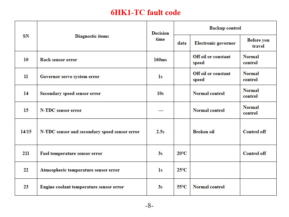
Camion dei pompieri Isuzu 6HK1-TC , anche chiamato Veicolo antincendio di soccorso Isuzu , Diagnosi e soluzioni dei codici di errore del motore. Il motore Isuzu 6HK1-TC utilizza l'avanzato sistema di controllo elettronico della pompa di iniezione TICS, mentre la centralina ECU (Engine Control Unit) è dotata di autodiagnosi. Quando il sistema rileva un guasto, la spia "CHECK ENGINE" si accende e il codice di errore corrispondente viene memorizzato. Comprendere l'interpretazione e le soluzioni per questi codici di errore può migliorare efficacemente l'efficienza della manutenzione del motore. Codici di errore comuni e soluzioni Codici di errore della serie P P0101 (Circuito del sensore di flusso d'aria di massa basso) Controllare il sensore della temperatura del liquido di raffreddamento del motore e il relativo cablaggio. Verificare la tensione di alimentazione del sensore e il collegamento a massa. Sostituire la centralina o il sensore se necessario. P0102 (Circuito sensore di flusso d'aria di massa alto) Controllare la qualità del carburante e le condizioni del filtro. Pulire il sistema di alimentazione. Controllare il regolatore di pressione del carburante, la pompa del carburante e i circuiti degli iniettori. P0103 (Circuito sensore di flusso d'aria di massa A alto) Controllare il circuito del segnale del sensore per verificare la presenza di un cortocircuito. Testare lo stato operativo del sensore. Sostituire il sensore o la centralina, se necessario. Codici di errore digitali 10 (Errore sensore rack) Controllare il sensore del rack e il relativo cablaggio. Verificare la normale trasmissione del segnale. 11 (Errore del sistema servo del regolatore di velocità) Controllare lo stato operativo del servosistema del regolatore di velocità. Testare i collegamenti dei circuiti correlati. 14 (Errore sensore velocità ausiliario) Controllare la posizione di installazione del sensore di velocità ausiliario. Testare l'uscita del segnale del sensore. 15 (Errore sensore N-TDC) Controllare la connessione del sensore N-TDC Verificare l'accuratezza del segnale Manutenzione del sistema e misure preventive SN Articoli diagnostici Tempo di decisione Controllo di backup dati regolatore elettronico Prima di partire 10 Errore del sensore del rack 160 ms Fuori olio o velocità costante Controllo normale 11 Errore del sistema servo del governatore 1s Fuori olio o velocità costante Controllo normale 14 Errore del sensore di velocità secondario 10 secondi Controllo normale Controllo normale 15 Errore del sensore N-TDC — Controllo normale Controllo normale 14/15 Errore del sensore N-TDC e del sensore di velocità secondario 2,5 secondi Olio rotto Controllo disattivato 211 Errore del sensore della temperatura del carburante 3 secondi 20℃ Controllo disattivato 22 Errore del sensore della temperatura atmosferica 1s 25℃ 23 Errore del sensore della temperatura del liquido di raffreddamento del motore 3 secondi 55℃ Controllo normale Connettore Terminale n. Segnale Diametro/cope...
Dettagli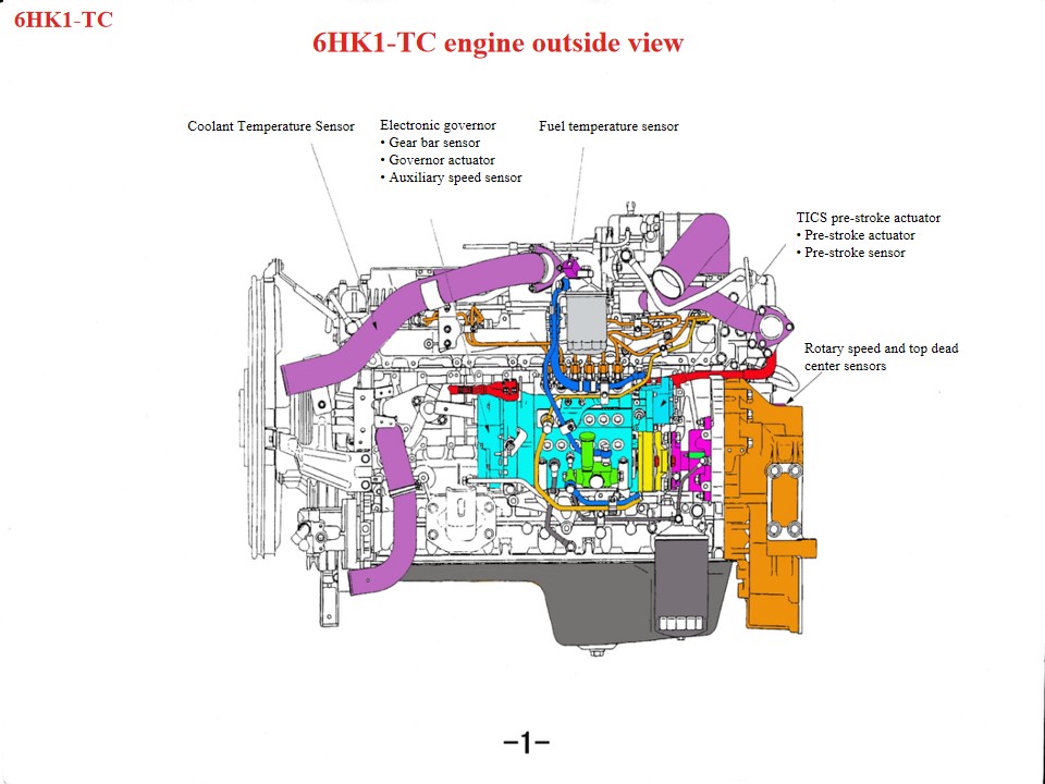
Veicoli antincendio Isuzu 6HK1 , anche chiamato Camion dei vigili del fuoco Isuzu , Se il motore di un camion dei pompieri Isuzu si surriscalda, è necessario controllare innanzitutto le seguenti aree: 1. Sistema di raffreddamento: problemi come una ventola danneggiata, un radiatore intasato, un termostato danneggiato o una quantità insufficiente di liquido di raffreddamento possono contribuire al surriscaldamento del motore. 2. Qualità e quantità dell'olio: anche una scarsa qualità dell'olio o una quantità insufficiente possono causare il surriscaldamento del motore. 3. Anche guasti meccanici come scoppio del cilindro, crepe nella canna del cilindro o crepe nella canna del cilindro possono causare questo fenomeno. Essendo un propulsore diesel per impieghi gravosi, il motore Isuzu 6HK1 richiede il rigoroso rispetto delle specifiche tecniche per la manutenzione. I punti chiave sono i seguenti: 1. Comprensione strutturale e specifiche di smontaggio e montaggio Meccanismo albero motore-biella La canna del cilindro presenta un design a accoppiamento libero, che richiede l'uso di utensili speciali per evitare che cada durante lo smontaggio e il montaggio. Il gioco standard è compreso tra 0,122 e 0,156 mm. Il diametro esterno del pistone ha una tolleranza ristretta (114,894–114,909 mm). Durante l'installazione, prestare attenzione al senso di apertura delle fasce elastiche e alla regolazione dei "tre giochi" (gioco terminale, gioco laterale e gioco posteriore). Il basamento inferiore è una struttura monoblocco e deve essere sollevato durante la manutenzione per evitare deformazioni. Allineamento del sistema di distribuzione Durante il montaggio del cambio, allineare i segni dell'ingranaggio dell'albero motore e dell'ingranaggio intermedio. Il segno B sull'albero a camme deve essere a filo con la superficie della testata. Il motore deve trovarsi al punto morto superiore di compressione sul primo cilindro. Durante l'installazione della pompa di iniezione del carburante, allineare l'indicatore di fasatura con il punto S sul connettore e allineare il segno dell'anticipo dell'iniezione con l'indicatore del corpo della pompa. • Il motore lineare a corrente continua spinge la bobina verso l'alto e verso il basso in base al segnale di uscita dell'unità di controllo. • La biella installata sul gruppo bobina trasmette il movimento verticale della bobina al blocco di collegamento, che è installato all'estremità della cremagliera. Sotto la spinta del blocco di collegamento, la cremagliera si muove a sinistra e a destra per modificare la quantità di carburante iniettata. Quando il gruppo bobina si muove verso l'alto, il collegamento spinge la cremagliera per aumentare la direzione dell'olio; viceversa, quando il gruppo bobina si muove verso il basso, la cremagliera si muove nella direzione di riduzione dell'olio, e la funzione della colonna è quella di convertire il movimento verticale all'altezza della cremagliera. • Il blocco di rame è montato sulla parte superior...
Dettagli
Per favore, continua a leggere, resta aggiornato, iscriviti e saremo lieti di conoscere la tua opinione.

 Rete IPv6 supportata

 italiano
 English
 français
 Deutsch
 русский
 español
 português
 Nederlands
 العربية
 日本語
日本語 한국의
한국의 Türkçe
 Melayu
 ไทย
ไทย Tiếng Việt
 Indonesia
  中文
中文 қазақ
қазақ Filipino
 မြန်မာ
 српски