Lascia un messaggio
Se sei interessato ai nostri prodotti e desideri maggiori dettagli, lascia un messaggio qui, ti risponderemo il prima possibile.

Fire Truck Tank Baffles Explained: Structure, Working Principle and Applications
Fire truck tank baffles work on the principles of slosh suppression and energy dissipation in fluid mechanics. When a fire truck accelerates, brakes, or turns during driving, the water inside the tank generates severe sloshing forces. By installing perforated partitions inside the tank, baffles divide the large water volume into multiple smaller compartments. The orifice throttling effect dissipates the sloshing kinetic energy, while the rigid support of the partitions strengthens the structural stability of the tank.
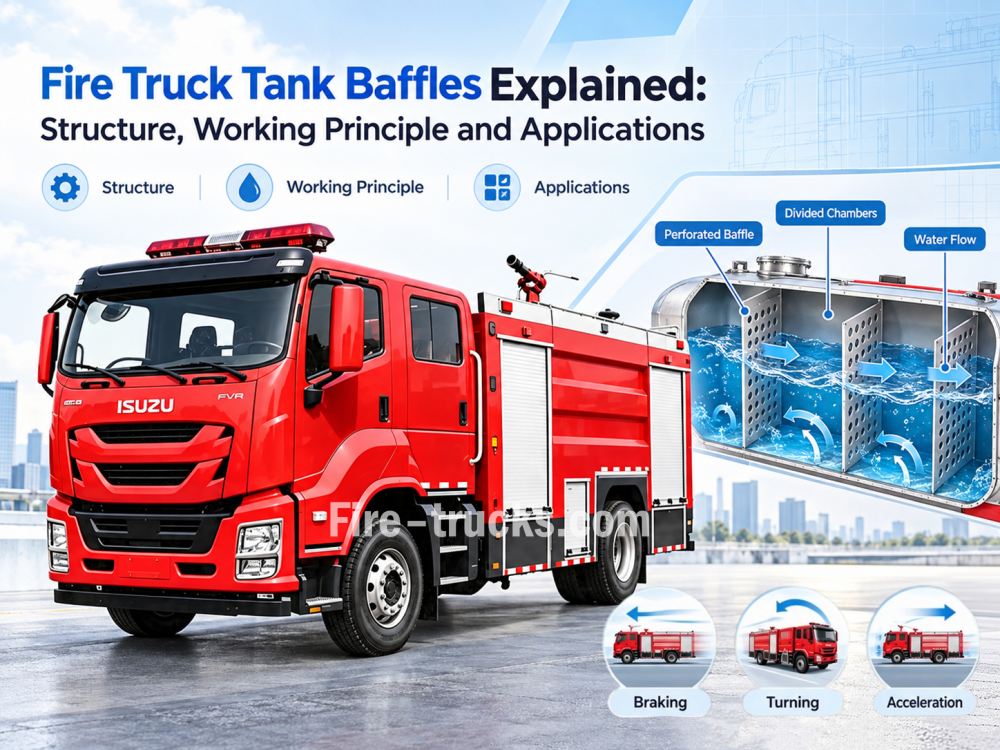
The structural design and working principle of fire truck tank baffles are a key concern for many customers, especially their impact on driving safety and tank service life. Let's take a closer look today.
1. Suppress liquid sloshing: Divide the water inside the tank into multiple independent compartments, limiting the free flow range of water in both longitudinal and transverse directions, and reducing sloshing amplitude.
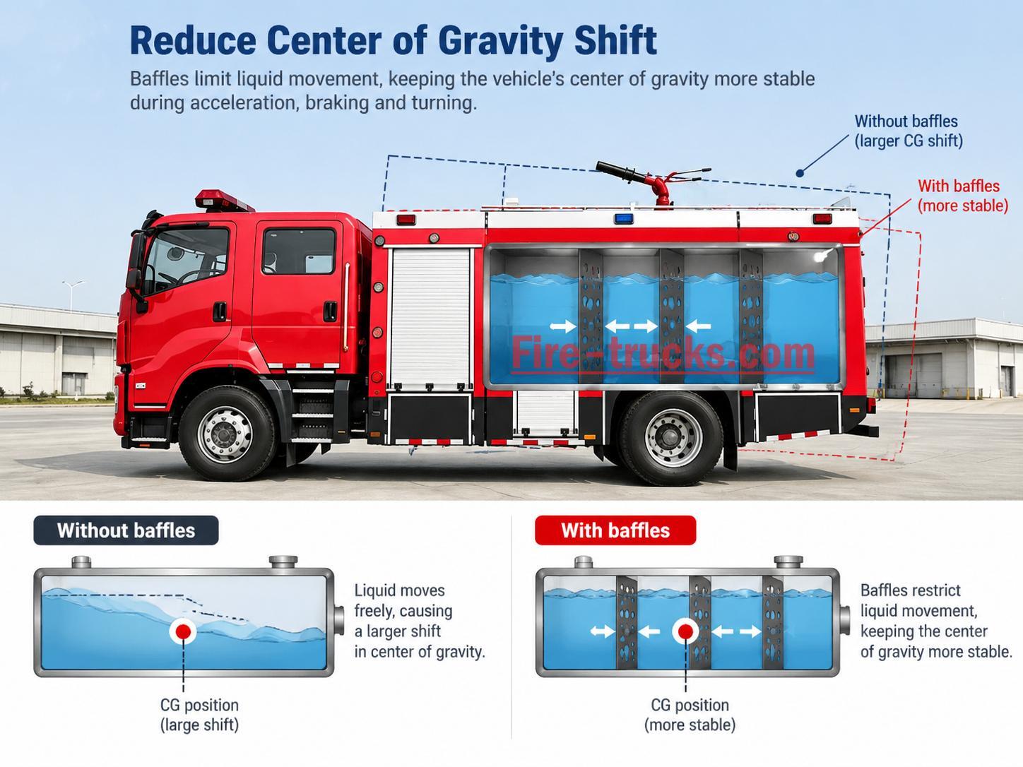
2. Reduce center of gravity shift: Dissipate sloshing kinetic energy through orifice throttling, slowing the severe shift of the water's center of gravity caused by vehicle movement, and reducing rollover risk.
3. Enhance tank stiffness: Baffles are welded to the tank walls, forming an internal reinforcing structure that improves the tank's resistance to water pressure deformation and mechanical impact.
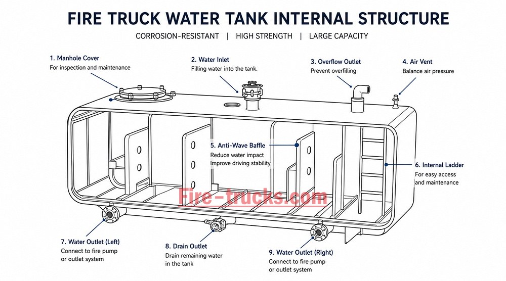
Segmentation principle: Baffles are arranged longitudinally along the tank, typically at fixed intervals, dividing the internal space into multiple relatively independent compartments. Water flow between compartments must pass through the orifices on the baffles, significantly restricting the flow path.
Spacing design: Baffle spacing is typically determined by tank length and water capacity. Excessive spacing results in insufficient slosh suppression; spacing that is too small increases tank weight and reduces effective volume. Reasonable spacing design requires a balance between suppression effectiveness and lightweight construction.
Throttling principle: When water flows through the baffle orifices during sloshing, the flow cross-section suddenly narrows, velocity increases, and local resistance loss occurs. Friction and collision between water molecules and between water and orifice edges convert sloshing kinetic energy into heat and dissipate it.
Damping effect: Smaller orifices provide stronger throttling and damping, resulting in better slosh suppression, but also greater resistance to water flow, which may affect filling and discharge speed. Therefore, orifice size must be determined based on actual operational requirements.
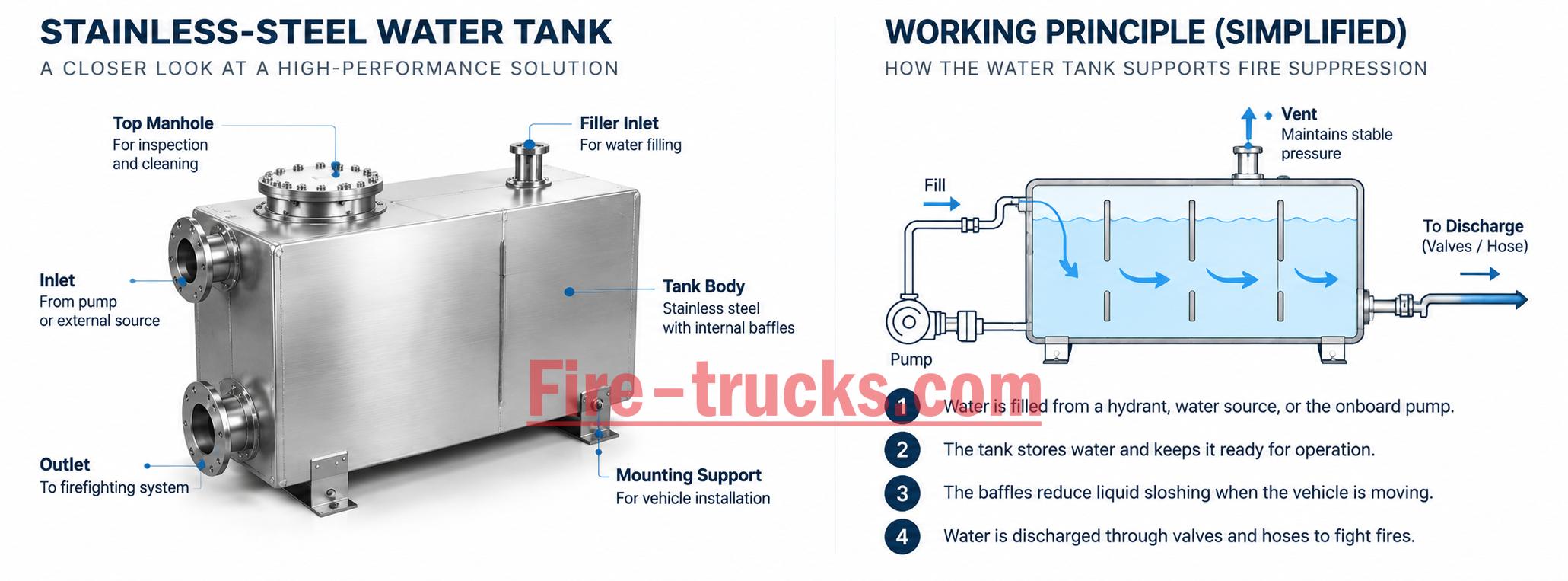
Welded connection: Baffles are welded to the tank inner walls around their perimeter, forming rigid support. When the tank is subjected to water pressure or external impact, the baffles act as reinforcing ribs to share the load and reduce local deformation of the tank walls.
Fatigue-resistant design: During long-term vehicle operation, the tank repeatedly bears alternating loads generated by water sloshing. Baffles effectively reduce stress concentration on the tank walls and extend the tank's fatigue life.
◊ To provide customers with more complete fire truck tank designs, CEEC factory focuses on the following key processes in baffle manufacturing:
| Structural Element | Material/Process | Function |
| Plate body | Carbon steel / stainless steel, 3–5 mm thickness | Main partition structure, bears water pressure and impact |
| Orifices | Round holes / slotted holes, edge chamfered | Throttling and damping, allows limited flow between compartments |
| Reinforcing ribs | Folded edges or angle steel welded | Improves baffle stiffness, prevents deformation |
| Welding method | Continuous or intermittent welding (per design requirements) | Connects to tank walls, transfers loads |
| Anti-corrosion treatment | Same grade coating as tank | Prevents baffle corrosion from affecting water quality |
| Parameter | Typical Range | Description |
| Open area ratio | 20%–40% | Ratio of total orifice area to baffle area |
| Orifice diameter | 30–80 mm | Smaller diameter = stronger damping, but greater flow resistance |
| Orifice spacing | 100–200 mm | Affects damping uniformity |
| Orifice layout | Uniform distribution or denser in center | Optimizes slosh suppression effect |
◊ To help customers better understand the impact of baffle configuration on driving safety and tank service life, we provide the following comparison:
| Comparison Item | With Baffles | Without Baffles |
| Liquid sloshing amplitude | Small, restricted by compartments | Large, free flow |
| Center of gravity shift | Small, kinetic energy dissipated by damping | Large, strong impact force |
| Braking distance | Short, stable center of gravity | Long, large inertial impact |
| Rollover risk | Low | High |
| Tank fatigue life | Long, low stress concentration | Short, welds prone to cracking |
| Applicable scenarios | All fire truck tanks | Not suitable |
| Vehicle Type | Typical Baffle Quantity | Spacing Design | Typical Use |
| Light water tank fire truck | 2–3 | 1.5–2 m | Urban firefighting, rapid response |
| Medium foam fire truck | 3–4 | 1.5–2 m | Industrial firefighting, multi-purpose response |
| Heavy water supply fire truck | 4–6 | 1.5–2 m | Remote water supply, large-capacity transport |
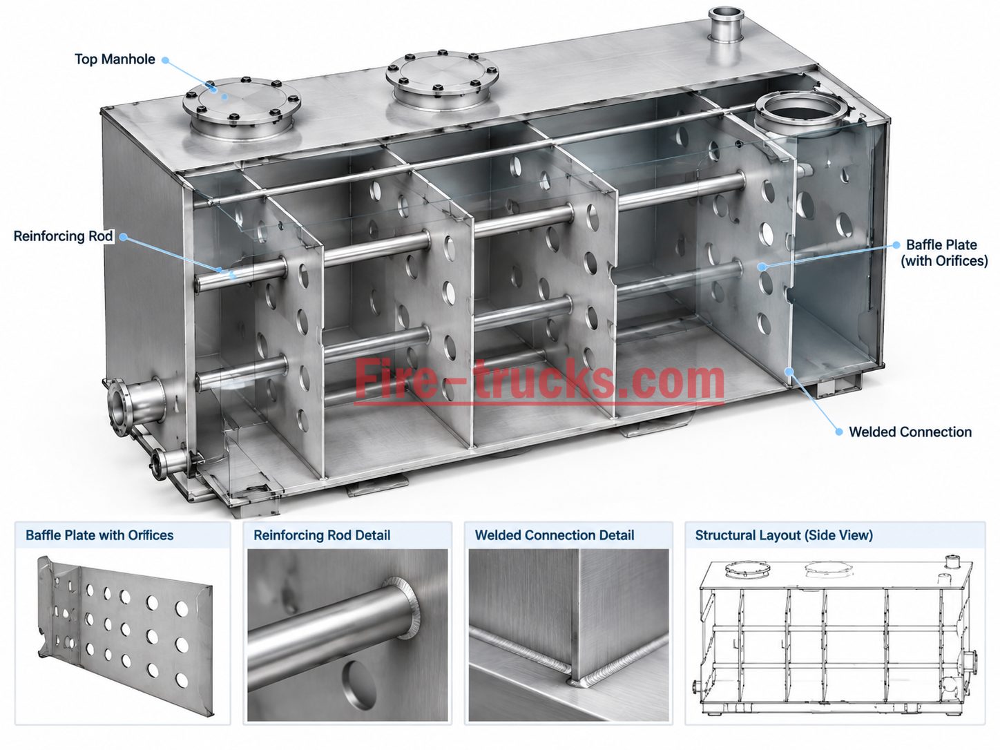
Q1: Why can't the orifices on the baffles be completely closed?
A: The orifices allow limited water flow between compartments so that water can pass through smoothly during tank filling and discharge. If the baffles were completely closed, water could not flow between compartments, and tank filling and discharge would be impossible. The orifices also provide throttling and damping to suppress sloshing.
Q2: How is baffle spacing determined?
A: Baffle spacing depends on tank length, water capacity, and vehicle operating conditions. Typical spacing is 1.5–2 meters, requiring a balance between slosh suppression effectiveness and tank lightweight construction. Excessive spacing results in insufficient suppression; spacing that is too small increases weight.
Q3: Do baffles affect tank cleaning?
A: Yes. Baffles divide the tank into multiple compartments, requiring cleaning compartment by compartment. Some designs include drain holes or hand holes at the bottom of the baffles to facilitate cleaning and drainage.
Q4: Must the baffle material match the tank material?
A: Generally yes. Baffles are welded to the tank, and matching materials ensure consistent welding performance and anti-corrosion treatment. If the tank is stainless steel, the baffles should also be stainless steel; if the tank is coated carbon steel, the baffles should receive the same grade of anti-corrosion treatment.
Q5: What are the consequences of baffle damage?
A: Baffle damage reduces slosh suppression effectiveness, allowing water to flow freely inside the tank. This increases center of gravity shift, extends braking distance, and raises rollover risk. At the same time, the tank walls lose internal support, and stress concentration may cause weld cracking. Damaged baffles should be repaired promptly.
Q6: Are there requirements for orifice orientation?
A: Orifice orientation generally has no strict requirements, but some designs use slotted holes or adjust orifice layout to optimize damping. The key parameters are open area ratio and orifice diameter, not orifice orientation.
Fire truck tank baffles are not simple partitions—they are a slosh suppression system based on fluid mechanics.
How they work: Liquid segmentation → Compartmentalization → Orifice throttling → Kinetic energy dissipation → Center of gravity stability → Driving safety
Key principle: Baffles divide the water volume, dissipate sloshing energy through orifices, and reinforce the tank structure—improving driving safety and extending tank fatigue life.


Potresti essere interessato alle seguenti informazioni
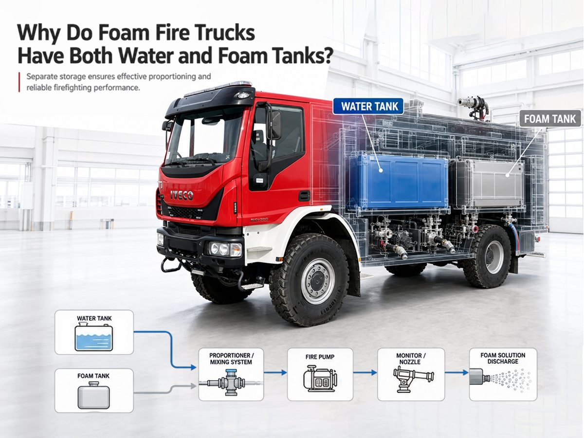
Gli automezzi antincendio a schiuma combinano un serbatoio dedicato per il concentrato di schiuma con un serbatoio d'acqua separato e un sistema di dosaggio di precisione. Utilizzano un sistema di dosaggio per introdurre il concentrato di schiuma nel flusso d'acqua a una concentrazione specificata, comunemente dell'1%, del 3% o del 6%, a seconda del concentrato di schiuma e dell'applicazione antincendio.doppio serbatoioIl design consente ai vigili del fuoco di utilizzare solo acqua quando non è necessaria la schiuma e di introdurre il concentrato di schiuma solo quando necessario. Ciò migliora la flessibilità operativa, aiuta a controllare il consumo di schiuma e permette di configurare il sistema antincendio per diversi tipi di incendio. Il principio di funzionamento e la tecnologia chiave degli automezzi antincendio a schiuma, in particolare il motivo per cui sono dotati sia di serbatoi d'acqua che di serbatoi per la schiuma, sono al centro dell'attenzione di molti clienti. Scopriamolo insieme oggi. Risposta rapida: Gli automezzi antincendio a schiuma utilizzano normalmente serbatoi separati per l'acqua e per il concentrato di schiuma, poiché acqua e concentrato sono necessari in proporzioni diverse e sono destinati a essere miscelati durante l'intervento, anziché essere conservati come soluzione premiscelata per lunghi periodi. Il serbatoio dell'acqua fornisce l'approvvigionamento idrico principale, mentre il serbatoio della schiuma contiene l'agente schiumogeno concentrato. Un sistema di dosaggio controlla la quantità di concentrato introdotta nel flusso d'acqua, consentendo al mezzo di passare dalla modalità di spegnimento con sola acqua a quella con schiuma. IO. Quali sono i componenti principali di un'autopompa antincendio con schiuma? 1. Serbatoio dell'acqua Costruzione resistente alla corrosione (acciaio al carbonio con rivestimento anticorrosione o acciaio inossidabile), capacità da 4.000 a 6.000 litri. Dotate di deflettori per ridurre le oscillazioni del liquido durante il movimento del veicolo e di supporti flessibili per assorbire le flessioni del telaio su terreni accidentati. 2. Serbatoio del concentratore di schiuma Struttura in acciaio inossidabile per resistere all'attacco chimico dei concentrati di schiuma attiva, con capacità tipica da 500 a 2.000 litri. A seconda del concentrato di schiuma e della progettazione del sistema, il serbatoio può includere caratteristiche quali sistemi di circolazione o agitazione per contribuire a mantenere le condizioni del concentrato durante lo stoccaggio. 3. Sistema di dosaggio della schiuma Un sistema di dosaggio che preleva il concentrato di schiuma dal sistema dedicatoschiumaIl sistema preleva il concentrato di schiuma e lo immette nel flusso d'acqua a una concentrazione specifica. A seconda del concentrato di schiuma e della configurazione del sistema, il dosaggio può avvenire tramite tecnologia a pressione bilanciata, a pompa o a effetto Venturi. 4. Pompa antincendio La pompa ...
Dettagli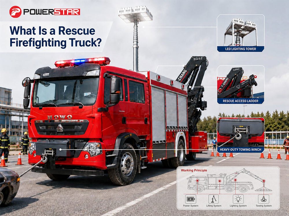
Un camion dei pompieri di soccorso è un veicolo di emergenza specializzato progettato per eseguire sia operazioni di spegnimento incendi che operazioni di salvataggio. A differenza dei normali camion dei pompieri che si concentrano principalmente sullo spegnimento degli incendi,autopompe antincendio di soccorsocombinare attrezzature antincendio con strumenti di soccorso, dispositivi di sollevamento e sollevamento, strumenti di taglio e divaricazione, verricelli, generatori e sistemi di illuminazione. Questo articolo spiega cos'è un'autopompa di soccorso antincendio, in cosa si differenzia dagli altri mezzi antincendio, quale equipaggiamento trasporta e quando viene impiegata. I. Che cos'è un camion dei pompieri di soccorso? Un'autopompa antincendio di soccorso è un veicolo di emergenza multifunzionale che combina capacità antincendio con attrezzature di soccorso specializzate. Viene utilizzata principalmente per fornire una risposta completa alle emergenze in caso di incidenti che coinvolgono persone, veicoli, edifici o impianti industriali. A seconda della configurazione del veicolo, i mezzi antincendio e di soccorso possono essere equipaggiati con un'ampia varietà di strumenti di soccorso e sistemi antincendio. La selezione effettiva delle attrezzature varia in base all'uso previsto del veicolo. Ad esempio, un veicolo configurato per il soccorso urbano può avere una configurazione delle attrezzature diversa da uno progettato per il soccorso industriale, la risposta ai terremoti o il recupero in caso di incidenti stradali. II. Quali attrezzature trasporta un camion dei pompieri di soccorso? L'equipaggiamento presente su un'autopompa antincendio dipende dalla progettazione del veicolo e dalla sua destinazione d'uso. Tuttavia, la maggior parte dei modelli può essere suddivisa in diverse categorie principali: attrezzature antincendio, strumenti di soccorso, apparecchiature elettriche, apparecchiature di illuminazione, dispositivi di sollevamento e traino e dispositivi di protezione individuale. 1. Attrezzatura antincendio Le attrezzature antincendio possono includere estintori, manichette antincendio, lance antincendio, pompe portatili, serbatoi d'acqua, sistemi antincendio a schiuma, monitor antincendio e altri strumenti di spegnimento. 2. Attrezzi idraulici di soccorso Gli strumenti idraulici di soccorso sono comunemente utilizzati nelle operazioni di soccorso in caso di incidenti stradali per tagliare, divaricare o sollevare le strutture danneggiate dei veicoli. Le attrezzature più comuni includono cesoie idrauliche, divaricatori idraulici e martinetti idraulici. 3. Generatore di corrente I generatori forniscono energia elettrica per strumenti di soccorso, apparecchiature di illuminazione, dispositivi di comunicazione e altre attrezzature quando non è disponibile una fonte di alimentazione esterna sul luogo dell'intervento. 4. Apparecchiature di illuminazione I sistemi di illuminazione di emergenza aiutano il personale di s...
Dettagli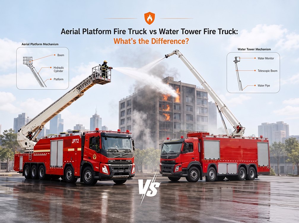
Quando si tratta di combattere gli incendi in edifici a molti piani, strutture industriali o grandi magazzini, gli autocarri antincendio aerei sono indispensabili. Ma tra i vari tipi di apparecchiature aeree, due spesso causano confusione: ilautocarro antincendio con piattaforma aerea e ilautocarro antincendio con torre d'acqua. Sebbene possano sembrare simili a prima vista—entrambi sono dotati di bracci idraulici e sono progettati per interventi antincendio in quota—svolgono missioni fondamentalmente diverse. Questo articolo analizza le differenze principali tra questi due tipi di veicoli, aiutando i professionisti dei servizi antincendio, i responsabili degli acquisti e i distributori di attrezzature a prendere decisioni informate in base alle esigenze operative. I. Cosa sono gli autocarri con piattaforma aerea? Secondo lo standard nazionale cinese GB 7956.12-2015, entrambi i veicoli rientrano nella categoria deiveicoli antincendio aerei—veicoli dotati di bracci elevabili, piattaforme girevoli e attrezzature antincendio per operazioni ad alta quota. Tuttavia, le loro definizioni specifiche evidenziano una distinzione fondamentale. Autocarro antincendio con piattaforma aerea Un autocarro antincendio con piattaforma aerea è dotato di un braccio combinato pieghevole o pieghevole-telescopico, una piattaforma per il personale, una piattaforma girevole e dispositivi antincendio. La caratteristica distintiva è lapiattaforma di lavoro (cestello) all'estremità del braccio, dove i vigili del fuoco possono stare per effettuare operazioni di soccorso e antincendio. Caratteristiche principali:• Dotato di una piattaforma che può trasportareda 750 libbre a oltre 1.500 libbre di personale e attrezzature• Progettato sia per ilsoccorso che per l'antincendio—i vigili del fuoco possono operare direttamente dalla piattaforma• La piattaforma può essere utilizzata con dispositivi di controllo della discesa, verricelli idraulici o scivoli di soccorso• Maggiore portata orizzontale e maggiore ampiezza operativa rispetto alle torri d'acqua II. Cosa sono gli autocarri antincendio con torre d'acqua? Un autocarro antincendio con torre d'acqua è dotato di un braccio combinato pieghevole o pieghevole-telescopico, una piattaforma girevole e dispositivi antincendio—senza piattaforma per il personale. Al suo posto, all'estremità del braccio è montato un monitor antincendio (cannone ad acqua), che può essere controllato a distanza da terra. Caratteristiche principali:•Nessuna piattaforma per il personale—i vigili del fuoco operano da terra tramite controllo remoto• Concentrato esclusivamente sulcontenimento degli incendi in quota, non sul soccorso• Eroga un flusso d'acqua eccezionalmente elevato—superando i 2.000 galloni al minutosu molti modelli industriali• Progettato per la protezione antincendio industriale dove non è richiesta la capacità di soccorso III. Confronto affiancato Caratteristica Autoscala antincendio con piattaforma aerea Automezzo antincendio con torre d...
Dettagli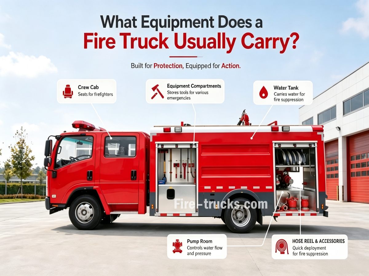
Un camion dei pompieri trasporta generalmente attrezzature per lo spegnimento degli incendi, l'approvvigionamento idrico, il soccorso e la protezione della sicurezza. Le attrezzature comuni includono pompe antincendio, serbatoi d'acqua, manichette antincendio, lance antincendio, monitor antincendio, valvole, scale antincendio, strumenti di soccorso, dispositivi di protezione e dispositivi di comunicazione. Questo articolo analizza sistematicamente la classificazione, le funzioni e le considerazioni sulla selezione delle attrezzature standardcamion dei pompieriattrezzature, aiutando i professionisti degli acquisti e gli utenti finali a comprendere completamente le configurazioni dei veicoli antincendio. I. Classificazione delle attrezzature dei camion dei pompieri 1. Attrezzature antincendio— Strumenti fondamentali per lo spegnimento diretto degli incendi, tra cui lance antincendio, monitor antincendio, manichette antincendio, divisori d'acqua e adattatori. 2. Attrezzature per soccorso e apertura di varchi— Strumenti per creare vie di accesso durante le operazioni di soccorso e spegnimento incendi, tra cui strumenti idraulici di soccorso, asce antincendio, leve, piedi di porco, seghe troncatrici e motoseghe. 3. Attrezzature di soccorso e salvataggio della vita— Attrezzature per la ricerca, il trasferimento e la protezione del personale, tra cui barelle, corde di soccorso, ganci di sicurezza, dispositivi di controllo della discesa, autorespiratori a circuito aperto (SCBA) e bombole d'aria di riserva. 4. Attrezzature per l'estrazione dei fumi e l'illuminazione— Attrezzature per migliorare le condizioni sul luogo dell'incendio, tra cui estrattori di fumo, torri d'illuminazione mobili e fari portatili di ricerca ad alta intensità. 5. Dispositivi di protezione individuale (DPI)— Equipaggiamento per proteggere la sicurezza dei vigili del fuoco, tra cui caschi, indumenti protettivi strutturali per antincendio, guanti, stivali e cinture di sicurezza. 6. Attrezzature di comunicazione e ricognizione— Attrezzature per la raccolta di informazioni sul luogo dell'incendio e il coordinamento del comando, tra cui radio ricetrasmittenti, termocamere e rilevatori di gas tossici. II. Attrezzature antincendio sui camion dei pompieri 1. Pompa antincendio La pompa antincendio è la fonte di energia per tutte le operazioni di spegnimento incendi. Pressurizza meccanicamente l'acqua, fornendole energia cinetica sufficiente per completare l'intero processo di "aspirazione → pressurizzazione → erogazione → scarico". Specifiche tipiche delle pompe antincendio: •Pompa antincendio a pressione standard (tipo CB10/30):Portata ≥30L/s, pressione nominale 1,0MPa, installazione posteriore. Adatta per autobotti d'acqua standard e camion antincendio a schiuma, soddisfa la maggior parte dei requisiti di approvvigionamento idrico antincendio urbani e industriali. •Pompa antincendio a media/alta pressione:Portata a bassa pressione 30L/s a 1,0MPa, portata ad alta pressione 20L/s a 2,0MPa, ...
Dettagli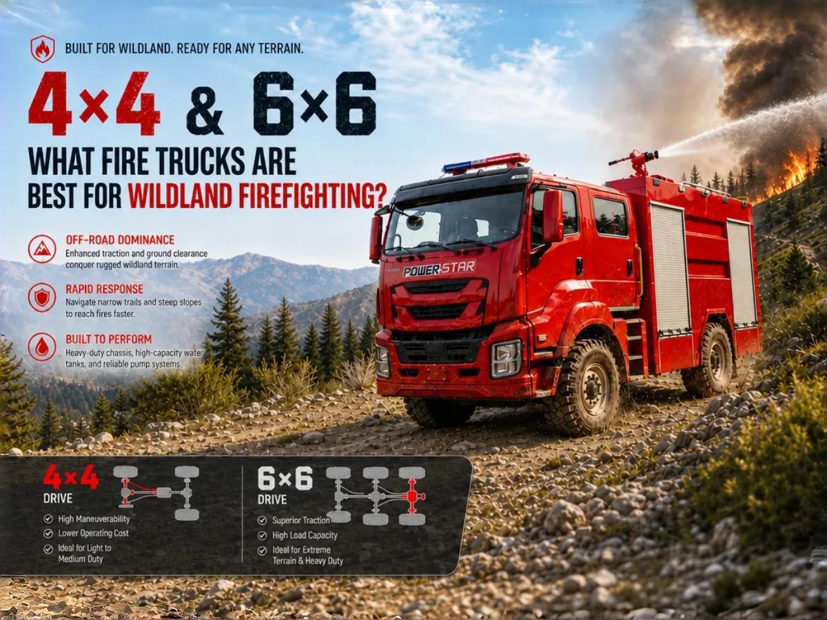
La lotta agli incendi boschivi presenta sfide fondamentalmente diverse rispetto alla lotta agli incendi strutturali. Nelle foreste remote, nelle praterie e nei terreni montuosi, i camion dei vigili del fuoco devono percorrere sentieri stretti, affrontare pendii ripidi e operare lontano da idranti o fonti d'acqua. Scegliere il giusto camion antincendio è una decisione strategica che influisce direttamente sui tempi di risposta, sulla sicurezza dell'equipaggio e sull'efficacia dello spegnimento degli incendi. Questo articolo fornisce un'analisi completa dei tipi di camion dei vigili del fuoco più adatti alla lotta agli incendi boschivi, delle loro caratteristiche principali e dei metodi di selezione, aiutandoti a prendere la decisione giusta in base ai tuoi specifici requisiti operativi. Risposta rapida Gli incendi boschivi sono caratterizzati da vaste aree incendiate, terreni complessi, fonti d'acqua limitate e condizioni stradali difficili, quindi non esiste un unico camion dei vigili del fuoco in grado di gestire tutti gli scenari di incendio forestale. In generale, la lotta agli incendi boschivi utilizza principalmente i seguenti tipi di camion dei vigili del fuoco: • Camion antincendio boschivo leggero: per l'accesso alle strade forestali e la risposta rapida• Camion antincendio boschivo fuoristrada 4×4: per terreni montuosi e collinari• Camion antincendio boschivo 6×6: per incendi forestali su larga scala e operazioni prolungate• Autobotti: per la fornitura continua d'acqua e il supporto• Camion antincendio a schiuma: per impianti petroliferi, attrezzature forestali o incendi speciali• Veicoli di soccorso: per comunicazioni, illuminazione, apertura di varchi e supporto logistico I. Perché gli incendi boschivi richiedono camion dei vigili del fuoco specializzati? Gli incendi boschivi differiscono fondamentalmente dagli incendi strutturali in diversi aspetti critici: Caratteristiche principali degli incendi boschivi:• Grandi aree incendiate che coprono ettari di terreno• Direzioni del vento che cambiano rapidamente• Terreni complessi e impervi• Accesso limitato o assente a idranti o fonti d'acqua• Strade forestali strette e non asfaltate• Difficili condizioni di comunicazione I camion dei vigili del fuoco urbani standard sono generalmente inadatti alla lotta agli incendi boschivi per i seguenti motivi: • Mancano della trazione 4×4 o integrale per strade di montagna non asfaltate e pendii ripidi;• Le dimensioni maggiori e la ridotta altezza da terra li rendono soggetti a rimanere bloccati su stretti sentieri forestali e terreni morbidi;• Le pompe urbane privilegiano un'elevata portata a pressione moderata, mentre le operazioni in ambiente boschivo richiedono alta pressione su lunghe stese di tubazioni con acqua limitata: un approccio fondamentalmente diverso. II. Tipi comuni di camion antincendio boschivi Tipo di camion dei vigili del fuoco Caratteristiche principali Scenari applicabili Camion antincendio boschivo leggero Elevata mobilità, dim...
Dettagli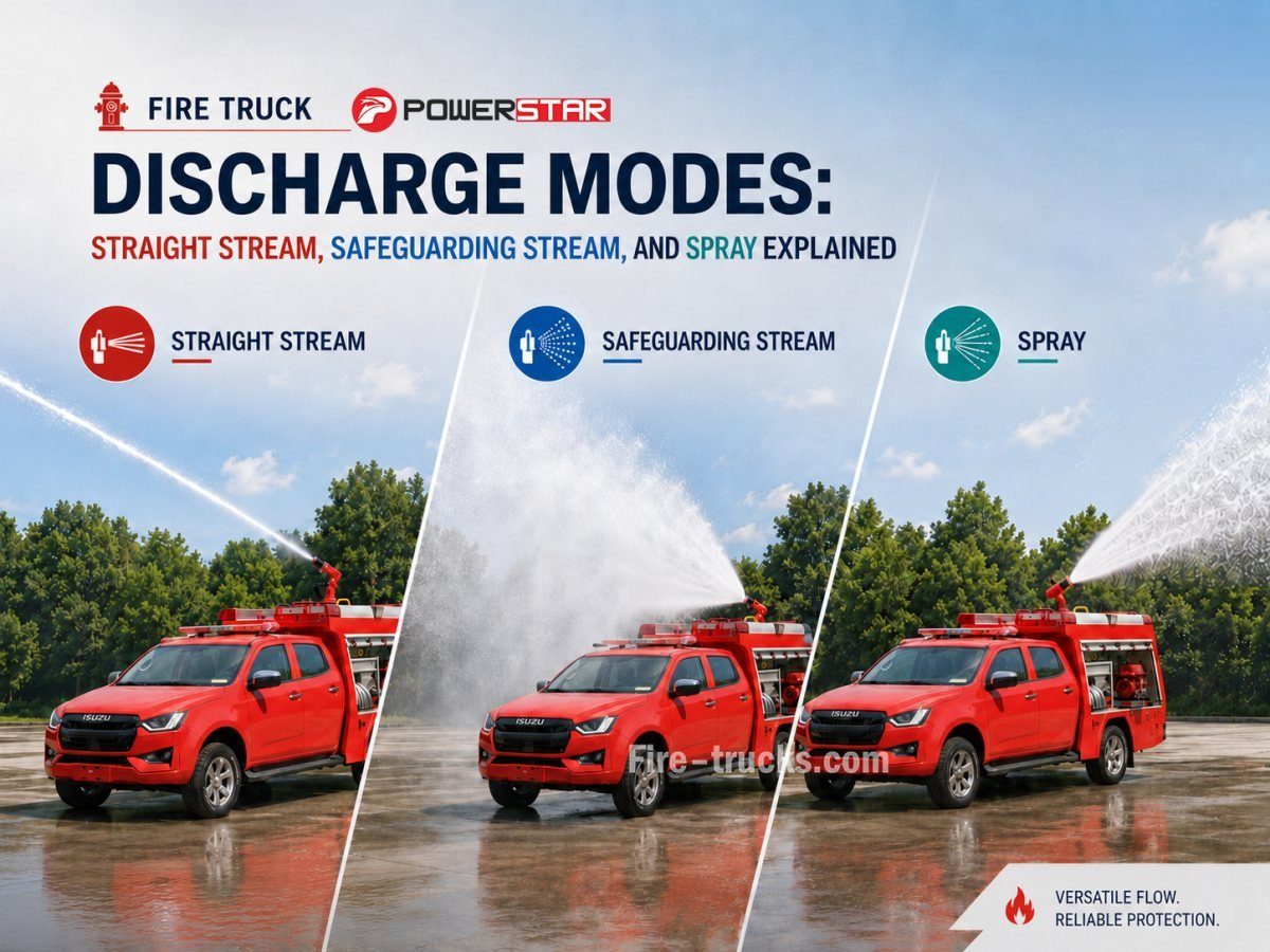
Nelle operazioni antincendio, la selezione della modalità di scarico determina direttamente l'efficienza di estinzione, la sicurezza operativa e l'efficacia del controllo dell'incendio. La maggior parte delle persone non sa che autopompa antincendio gli ugelli possono passare tra tre modalità di scarico principali: getto pieno, getto nebulizzato e getto di protezione. Le diverse modalità variano notevolmente per schema di flusso, portata, forza d'impatto e area di copertura, e ciascuna corrisponde a scenari antincendio applicabili completamente diversi. Questo articolo, basato sugli standard professionali delle operazioni antincendio, analizza in modo completo i principi, le caratteristiche principali e gli scenari applicabili delle tre modalità di scarico, aiutando i nostri clienti a padroneggiare sistematicamente le tecniche di scarico delle autopompe antincendio. I. Perché le autopompe antincendio necessitano di diverse modalità di scarico? Il getto pieno, il getto nebulizzato e il getto di protezione corrispondono a tre diversi meccanismi di estinzione: estinzione tramite impatto, soffocamento tramite vaporizzazione e protezione dalle radiazioni termiche. I vigili del fuoco devono effettuare il cambio in modo flessibile in base alle condizioni del luogo. Quindi, perché non possiamo continuare a usare un solo tipo di getto? 1. La diversità dei tipi di incendio richiede diverse forme di agenti estinguenti Diversi tipi di incendio presentano caratteristiche di combustione differenti, che determinano il metodo di estinzione appropriato: • Gli incendi di materiali solidi di classe A richiedono l'impatto del getto pieno per rompere i materiali in combustione e penetrare per il raffreddamento interno; • Gli incendi di liquidi di classe B non possono utilizzare l'impatto del getto pieno (che provoca schizzi e diffonde l'incendio), ma devono usare il getto di protezione o il getto nebulizzato per copertura e diluizione; • Gli incendi elettrici sotto tensione di classe E possono utilizzare solo il getto nebulizzato, poiché le gocce d'acqua fini non formano un percorso conduttivo continuo; • Gli incendi in spazi chiusi richiedono il getto nebulizzato per riempire l'intero ambiente, ottenendo l'estinzione tramite assorbimento del calore di vaporizzazione e soffocamento. Nessuna singola modalità può adattarsi a tutti i tipi di incendio. 2. Le diverse fasi dello stesso incendio richiedono approcci tattici differenti Anche per lo stesso incendio, fasi diverse richiedono modalità di scarico differenti: • Nella fase iniziale, quando l'incendio è intenso, è necessario il getto pieno per colpire a lunga distanza il punto dell'incendio e ottenere una rapida soppressione; • Durante l'avanzamento, è necessario il getto di protezione per formare una barriera a cortina d'acqua che blocchi la radiazione termica e protegga il personale; • Prima di entrare in una stanza, è necessario il getto nebulizzato per raffreddare e diluire fumo e gas, creando le condizioni per l...
Dettagli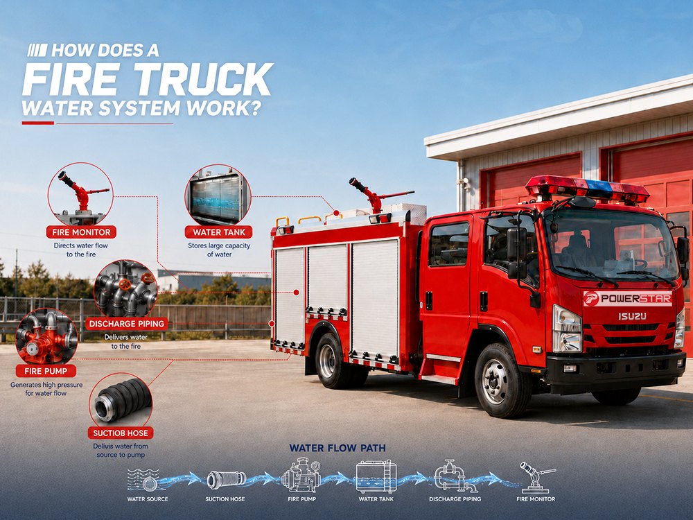
Il sistema idraulico dell'autopompa antincendio è il cuore di ogni operazione di spegnimento incendi. Dirige con precisione l'acqua dal serbatoio o da una fonte esterna attraverso la pompa, le valvole e le tubazioni per fornire acqua ad alta pressione o schiuma sul luogo dell'incendio, sia che si tratti di un incendio in un edificio a molti piani in un denso centro urbano sia di un incendio di un serbatoio di stoccaggio petrolchimico in una zona industriale. autopompa antincendio Il sistema idraulico dell'autopompa antincendio è composto da molteplici componenti che lavorano insieme: pompa antincendio, serbatoio dell'acqua, tubo di aspirazione, tubazioni di mandata, valvole, raccordo di diramazione, raccordo collettore, filtro, monitor antincendio, raccordi per manichette e altro ancora. Il percorso completo del flusso è: Serbatoio dell'acqua → Tubo di aspirazione → Filtro → Pompa antincendio → Sistema di regolazione della pressione → Collettore di mandata → Valvole → Raccordo di diramazione → Monitor antincendio / Raccordi per manichette → Ugello Questo articolo spiega ogni componente del sistema idraulico e come lavorano insieme per fornire acqua alla pressione e al flusso corretti. I. Componenti principali del sistema idraulico Serbatoio dell'acqua Conserva la riserva d'acqua a bordo. ● Capacità: Tipicamente 2.000–12.000 litri. ● Erogazione: Alimenta la pompa attraverso le tubazioni di aspirazione. ● Caratteristiche: Paratie anti-sciabordio per la stabilità del veicolo, filtro per filtrare i detriti e sistema di adescamento per l'aspirazione da fonti d'acqua naturali. Pompa antincendio Una pompa centrifuga azionata dal motore del camion tramite PTO; a uno o più stadi, in ghisa o bronzo. ● Classi di pressione: Disponibile con valori nominali standard di 0,8 MPa, 1,0 MPa, 1,2 MPa e 1,4 MPa, conformi ai requisiti tipici della lotta antincendio. ● Portate: Vanno da 1.200 a 6.000 L/min, con curve di prestazione ottimizzate sia per operazioni ad alta pressione sia per operazioni ad alto volume. Valvole e tubazioni Una rete di tubi e valvole che controlla la direzione e il volume del flusso d'acqua. ● Valvola di aspirazione: Collega la pompa a fonti d'acqua esterne (idrante o punto di aspirazione) ● Valvola serbatoio-pompa: Consente alla pompa di prelevare acqua direttamente dal serbatoio a bordo ● Valvole di mandata: Controllano il flusso d'acqua verso manichette e ugelli II. Come funziona il sistema idraulico dell'autopompa antincendio Fase 1: Presa d'acqua e adescamento L'acqua entra nel sistema dal serbatoio a bordo, dall'idrante antincendio o da fonti d'acqua naturali (laghi, fiumi, stagni). Quando si aspira da fonti naturali, il sistema di adescamento (pompa a vuoto) rimuove l'aria dal tubo di aspirazione, creando un vuoto che consente alla pressione atmosferica di spingere l'acqua nella pompa. Un filtro trattiene i detriti per proteggere la pompa e una valvola di ritegno impedisce il riflusso. Passaggio 2: Pressurizzazione della pompa La pomp...
Dettagli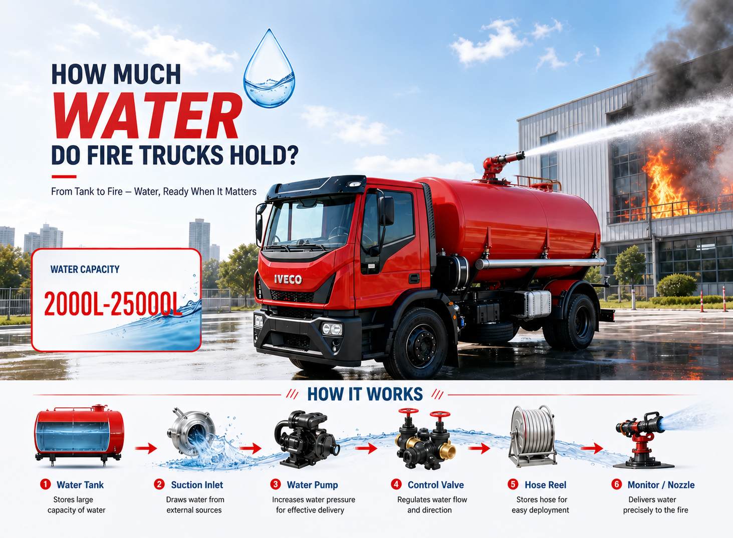
Quanta acqua può trasportare un'autopompa antincendio? Questa è una delle prime domande che i nostri clienti si pongono quando selezionano un'autopompa antincendio. Non esiste un numero fisso unico: dipende dal tipo di veicolo, dalla capacità del telaio, dallo scopo progettuale e dalle normative regionali, con valori che vanno dalle unità leggere da 2.000 litri fino alle autopompe antincendio industriali da 25.000 litri. Tuttavia, un serbatoio più grande non significa sempre prestazioni migliori; veicolo antincendio la capacità del serbatoio dell'acqua deve essere adeguatamente abbinata alla portata della pompa, alla portata di scarico del monitor e alla capacità del telaio per ottenere risultati efficaci nello spegnimento degli incendi. Questo articolo parte dai fondamenti della capacità del serbatoio dell'acqua delle autopompe antincendio, analizza gli intervalli di stoccaggio tipici per diversi tipi di veicoli, esamina i fattori chiave che influenzano la progettazione del serbatoio e fornisce indicazioni pratiche per l'acquisto. Punti chiave: La capacità del serbatoio dell'acqua delle autopompe antincendio varia tipicamente da 2.000 a 25.000 litri Diversi tipi di autopompe antincendio hanno capacità del serbatoio differenti Un serbatoio più grande non significa una migliore capacità di spegnimento degli incendi La capacità del serbatoio deve essere abbinata alla portata della pompa, alla portata del monitor e alla capacità del telaio Lo spegnimento degli incendi industriali richiede generalmente serbatoi grandi, mentre lo spegnimento degli incendi municipali dà priorità alla manovrabilità » I. Tre tipi fondamentali di serbatoi d'acqua per autopompe antincendio Autopompe:Questi sono i veicoli antincendio municipali più comuni. Si affidano principalmente agli idranti per l'approvvigionamento idrico e trasportano circa 1.900–3.800 litri d'acqua a bordo per l'attacco iniziale. Il componente principale di questi veicoli è la pompa, non il serbatoio: sono progettati per erogare acqua pressurizzata una volta collegati a un idrante. Autobotti (trasportatori d'acqua):Questi veicoli sono dedicati al trasporto di grandi volumi d'acqua, con capacità del serbatoio generalmente superiori a 11.400 litri. Svolgono un ruolo fondamentale nelle aree rurali e remote dove gli idranti non sono disponibili, trasportando acqua dalle fonti idriche al luogo dell'incendio affinché le autopompe possano utilizzarla. Autopompe-autobotti:Questi veicoli combinano le funzioni di pompaggio e trasporto dell'acqua in un'unica unità. Possono sia erogare acqua per lo spegnimento degli incendi sia rifornire altri veicoli. Le capacità dei serbatoi variano generalmente da 5.700 a 11.400 litri, rendendoli una soluzione versatile per i vigili del fuoco. » II. Quanta acqua possono trasportare diversi tipi di autopompe antincendio? Tipo di autopompa antincendio Capacità tipica del serbatoio Applicazione principale Autopompa antincendio leggera 2.000–3.000 L Risposta rapida urbana, attacc...
Dettagli
Per favore, continua a leggere, resta aggiornato, iscriviti e saremo lieti di conoscere la tua opinione.

 Rete IPv6 supportata

 italiano
 English
 français
 Deutsch
 русский
 español
 português
 Nederlands
 العربية
 日本語
 한국의
 Türkçe
 Melayu
 ไทย
 Tiếng Việt
 Indonesia
 中文
 қазақ
 Filipino
 မြန်မာ
 српски