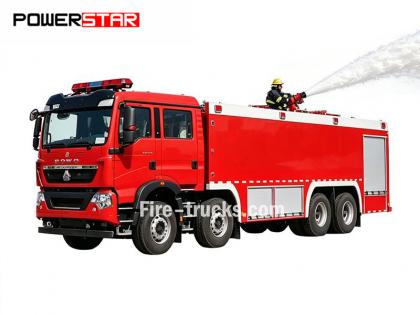
Lascia un messaggio
Se sei interessato ai nostri prodotti e desideri maggiori dettagli, lascia un messaggio qui, ti risponderemo il prima possibile.

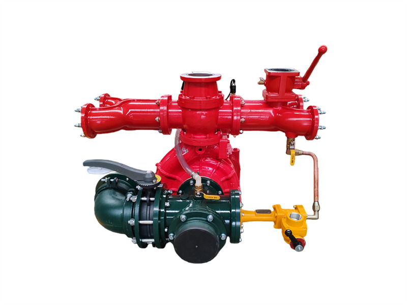
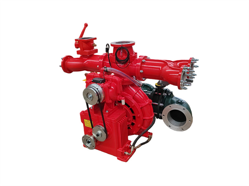
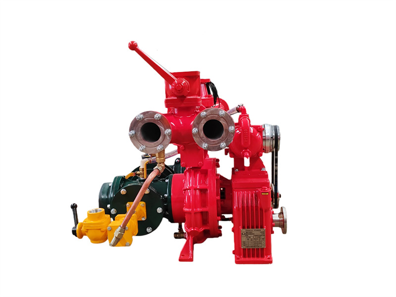
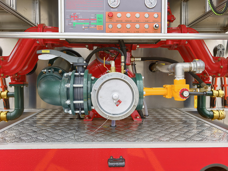
Il CB10/60-RS pompa antincendio montata su autocarro è composta da una pompa centrifuga monostadio a bassa pressione, una pompa del vuoto a doppio pistone, un dispositivo di disinnesto automatico della frizione elettromagnetica, un moltiplicatore di velocità, una tubazione di uscita con valvola di intercettazione e una tubazione di ingresso.
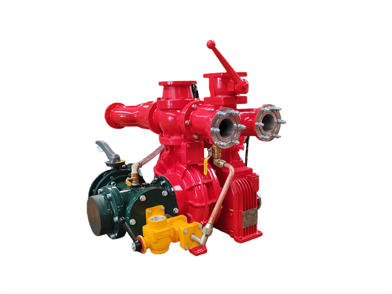 ♦ Struttura principale e funzione
(1) Pompa centrifuga monostadio a bassa pressione: Composta da un coperchio della pompa, corpo pompa, girante del primo stadio e albero della pompa, fornisce la pressione nominale e la portata nominale.
(2) Moltiplicatore di velocità: Il moltiplicatore di velocità della pompa antincendio montata su veicolo CB10/60-RS ha un rapporto di aumento della velocità convenzionale di 1,440.
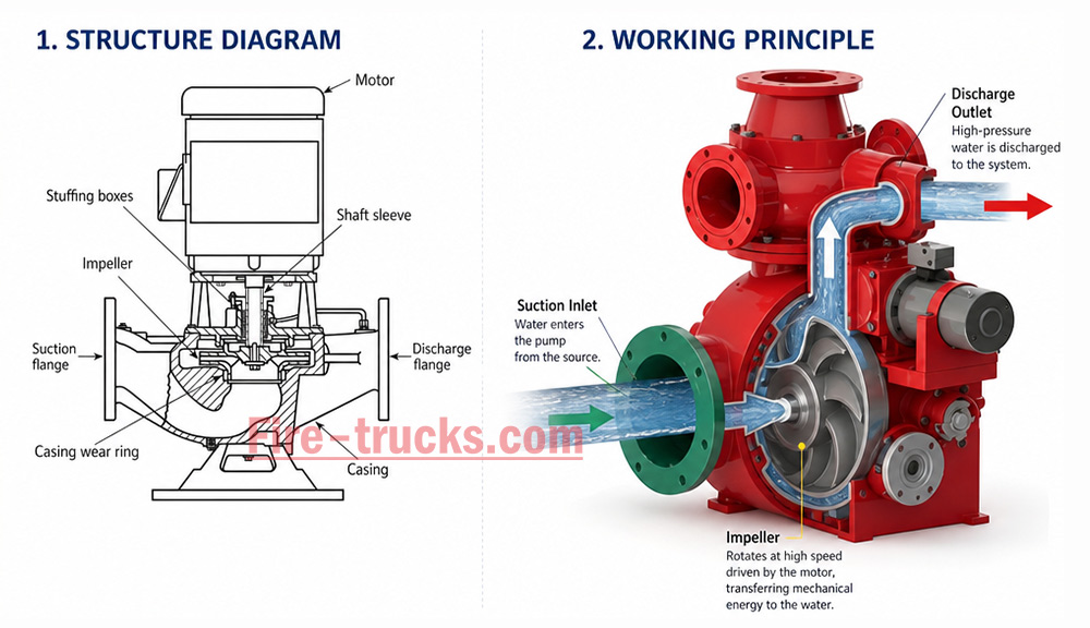
(3) Pompa del vuoto a doppio pistone: Composta principalmente da un pistone, corpo pompa, albero della pompa e ruota eccentrica. La ruota eccentrica è dotata di un'asta guida del pistone e di una camicia in acciaio del corpo pompa. Le valvole di ingresso e uscita sono installate su entrambe le estremità della pompa a pistone. Quando la frizione elettromagnetica si innesta, la pompa a pistone inizia a funzionare. Durante il funzionamento, l'azione eccentrica della ruota eccentrica fa muovere alternativamente il pistone, espellendo gradualmente l'aria dalla pompa e dalla tubazione, migliorando così la qualità dell'aria. Si crea un vuoto all'interno della cavità per raggiungere lo scopo dell'aspirazione dell'acqua.
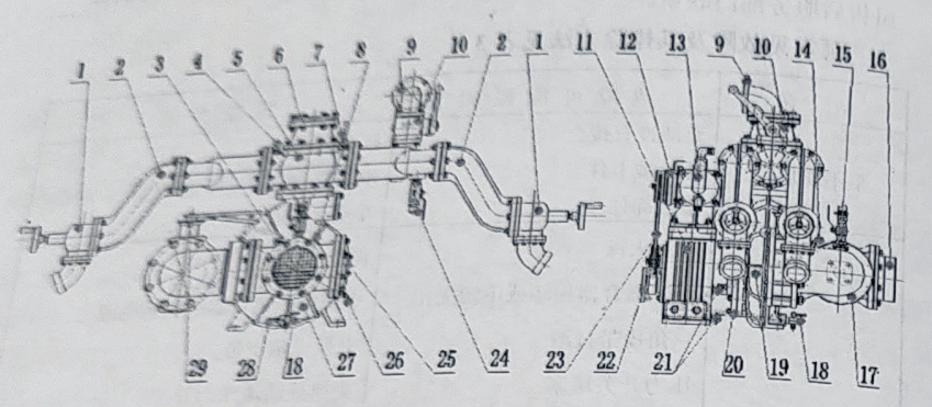
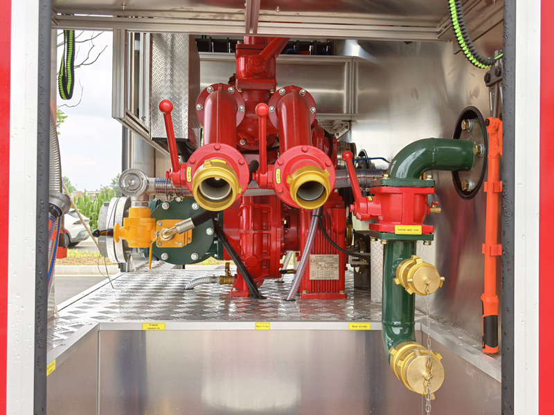
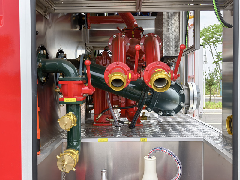
1. Valvola di intercettazione dell'uscita (4 pezzi); 2. Tubi dell'acqua di uscita sinistro e destro; 3. Raccordo di ritorno dell'acqua di raffreddamento del cambio; 4. Raccordo del manometro; 5. Valvola di ritegno dell'uscita; 6. Flangia del cannone ad acqua; 7. Pressostato dell'acqua; 8. Raccordo di ritorno dell'acqua in pressione di raffreddamento della presa di forza; 9. Flangia del serbatoio dell'acqua posteriore; 10. Valvola a sfera del serbatoio dell'acqua posteriore; 11. Cambio; 12. Frizione elettromagnetica e cablaggio; 13. Pompa di adescamento a pistone; 14. Raccordo del vacuometro; 15. Raccordo di adescamento del vuoto; 16. Interfaccia del tubo di ingresso; 17. Tubo a quattro vie di ingresso; 18. Valvola di scarico della pompa dell'acqua; 19. Tubo di ritorno dell'acqua in pressione di raffreddamento del cambio; 20. Tubo di ingresso dell'acqua in pressione di raffreddamento del cambio; 21. Valvola del livello dell'olio lubrificante del cambio; 22. Flangia di accoppiamento; 23. Cinghia di trasmissione; 24. Raccordo filettato dell'acqua in pressione del dosatore di schiuma (non disponibile sulle autocisterne dell'acqua); 25. Interfaccia del dosatore di schiuma; 26. Raccordo di uscita dell'acqua in pressione di raffreddamento della presa di forza; 27. Pompa antincendio per veicolo CB10/60; 28. Raccordo di uscita dell'acqua in pressione di raffreddamento del cambio; 29. Valvola a farfalla di ingresso posteriore
(4) Tubazione di uscita dell'acqua a bassa pressione e valvola di intercettazione:È composta da una valvola di ritegno dell'uscita dell'acqua a bassa pressione, tubi di uscita dell'acqua destro e sinistro, quattro tubi di uscita dell'acqua e quattro valvole di intercettazione dell'uscita dell'acqua.
(5) Tubazione di ingresso dell'acqua montata posteriormente:È composta da un tubo di ingresso a quattro vie, un filtro di ingresso, un raccordo di ingresso esterno e, su entrambi i lati del tubo di ingresso a quattro vie, il lato destro dispone di un'interfaccia per l'installazione di un dosatore di schiuma, mentre il lato sinistro è dotato di un gomito di ingresso posteriore rotante, una valvola a farfalla da 150mm e una flangia saldabile.
 ♦Specifiche
| Modello | Diametro di ingresso (mm) | Diametro di uscita (mm) | Vuoto massimo (kPa) | Calo del vuoto entro 1 minuto(MPa) | Tempo di aspirazione a profondità di 7m (s) |
| CB10/60-RS | Φ150 | Φ80X4 | ≥85 | ≤2.6 | ≤50 |
| Modello | Condizioni di lavoro | Profondità di aspirazione(m) | Portata(L/s) | Pressione(MPa) | Velocità dell'albero(giri/min) | Potenza dell'albero(kw) | Pressione massima di esercizio(MPa) |
| CB10/60-RS | 1 | 3 | 60 | 1.0 | 3200±50 | 99.71 | 1.082 |
| 2 | 42 | 1.3 | 3528+50 | 109.18 | - | ||
| 3 | 7 | 30 | 1.0 | 332650 | - | - |
♦ Funzionamento
1. Lavori preparatori prima del funzionamento
(1) Tutte le valvole di scarico della pompa devono essere chiuse;
(2) Per i veicoli antincendio con schiuma, la valvola a sfera della tubazione della schiuma e il dosatore di schiuma devono essere chiusi;
(3) Per i veicoli antincendio con schiuma, la valvola a sfera di iniezione dell'acqua del dosatore di schiuma sul lato destro del tubo di mandata deve essere chiusa;
(4) Chiudere la valvola a sfera di iniezione dell'acqua del serbatoio;
(5) Aprire la valvola di adescamento sulla tubazione di ingresso della pompa dell'acqua;
2. Adescamento
Quando la pompa dell'acqua aspira acqua, sono disponibili tre diversi metodi di funzionamento a seconda della fonte d'acqua:
(1) Funzionamento con alimentazione dell'acqua dal serbatoio:
Avviare la pompa antincendio, aprire la valvola a farfalla sulla tubazione di ingresso dell'acqua dal serbatoio alla pompa, aprire la valvola a sfera di mandata e regolare l'acceleratore manuale per impostare la velocità della pompa alla portata e alla pressione richieste.
(2) Funzionamento con alimentazione dell'acqua dall'idrante antincendio:
① Estrarre il tubo di aspirazione (o il tubo flessibile, il collettore dell'acqua) e la chiave per idrante antincendio.
② Collegare l'ingresso della pompa antincendio all'idrante antincendio utilizzando il tubo di aspirazione (o il tubo flessibile, il collettore dell'acqua).
③ Utilizzare la chiave per idrante per aprire la valvola dell'idrante, consentendo all'acqua di entrare nella pompa. Avviare la pompa antincendio, aprire la valvola a sfera di mandata e regolare l'acceleratore manuale per impostare la velocità della pompa alla portata e alla pressione richieste.
Nota: Quando si utilizza l'idrante per l'alimentazione dell'acqua, l'interruttore del vacuometro deve essere spento per primo; in caso contrario, il vacuometro verrà danneggiato.
(3) Funzionamento quando si aspira acqua da fiumi, stagni o pozzi:
① Rimuovere il tubo di aspirazione, il filtro e la chiave del tubo di aspirazione.
② Collegare il tubo di aspirazione alla lunghezza appropriata, installare il filtro all'estremità del tubo di aspirazione e installare l'altra estremità del tubo di aspirazione sull'ingresso della pompa antincendio. Immergere nell'acqua l'estremità con il filtro installato.
Nota: Non devono esserci perdite d'aria in alcun punto di collegamento del tubo di aspirazione. Il filtro deve essere immerso nella fonte d'acqua con una distanza di circa 0,5 metri dalla parte superiore del filtro alla superficie dell'acqua. Un'immersione troppo superficiale creerà vortici durante l'aspirazione dell'acqua, influenzando la portata. Tuttavia, non deve entrare in contatto con il fango del fondale del fiume per evitare l'aspirazione di fango e detriti, che potrebbero ostruire il tubo di aspirazione e danneggiare la pompa antincendio. La valvola a farfalla di ingresso posteriore deve essere chiusa prima dell'adescamento.
③ Avviare la pompa antincendio e attivare l'interruttore di alimentazione del dispositivo di adescamento. La frizione elettromagnetica si innesterà. Questo avvierà la pompa a pistoni. Regolare l'acceleratore manuale a circa 2500 giri/min. La pompa a pistoni creerà rapidamente il vuoto nel tubo di aspirazione e nella camera della pompa, aspirando acqua nella girante dello stadio a bassa pressione. La pressione dell'acqua verrà quindi indirizzata al pressostato del dispositivo di adescamento sull'uscita. Quando la pressione di uscita raggiunge 0,2 MPa, la frizione elettromagnetica si disinnesterà automaticamente, la pompa a pistoni si fermerà e la pompa antincendio inizierà a scaricare acqua. A questo punto, spegnere l'interruttore di alimentazione del dispositivo di adescamento.
Nota: Durante l'adescamento di una pompa antincendio in serie a bassa pressione, la velocità della pompa deve essere controllata a circa 2500 giri/min.
④ Regolare l'acceleratore manuale per impostare la velocità della pompa alla portata e alla pressione richieste.
Attenzione: Quando la pompa dell'acqua fornisce acqua normalmente, se si verifica un'emergenza ed è necessario chiudere temporaneamente la valvola di mandata o interrompere l'alimentazione dell'acqua, la velocità della pompa dell'acqua deve essere ridotta contemporaneamente alla velocità minima e il tempo non deve essere troppo lungo. In caso contrario, se la pompa dell'acqua funziona ma non fornisce acqua per troppo tempo, la temperatura dell'acqua all'interno della pompa aumenterà rapidamente, danneggiando i componenti interni della pompa.
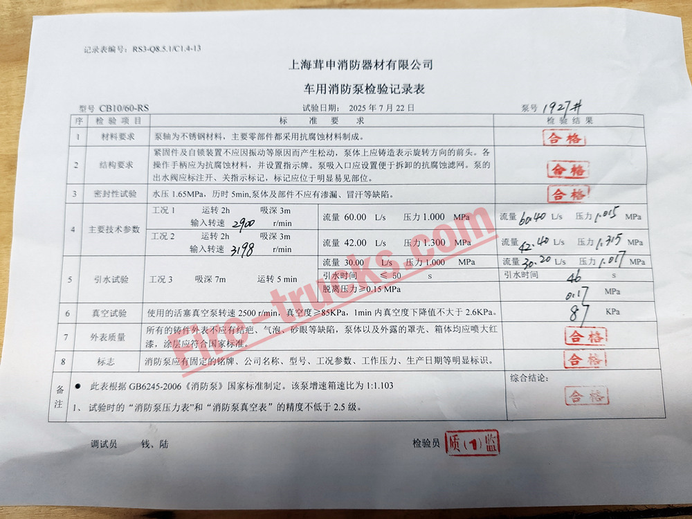
Ispezione della qualità prima della consegna
♦ Manutenzione e assistenza
1. Dopo aver utilizzato la pompa dell'acqua con acqua di mare, acqua eccessivamente inquinata, acqua corrosiva o miscele schiumose, farla funzionare con acqua pulita per almeno 10 minuti per eliminare il liquido residuo dalla pompa e dalle tubazioni.
2. Dopo ogni utilizzo della pompa dell'acqua, aprire tutte le valvole di scarico della pompa e delle tubazioni per scaricare tutta l'acqua rimanente. Quindi chiudere tutte le valvole.
3. Controllare trimestralmente il livello dell'olio del cambio. Se è inferiore al livello consigliato, rabboccare. Sostituire l'olio ogni due anni.
Nota: il grado dell'olio del cambio è: olio per ingranaggi ipoidi n. 18 oppure olio per ingranaggi 85W/90 per carichi medi.
4. Se l'acqua non viene aspirata entro il tempo specificato, arrestare la pompa a pistone e controllare tutti i collegamenti e le valvole per eventuali perdite. Eliminare eventuali perdite prima di riprendere il funzionamento.
♦Guasti comuni della pompa e metodi di risoluzione dei problemi
| Guasto | Possibili cause | Soluzioni per la risoluzione dei problemi |
| La pompa non si avvia |
1. Frizione della pompa non innestata 3. Pompa completamente congelata |
1. Innestare la frizione della pompa
|
| La pompa non riesce ad adescare l'acqua |
1. Profondità di aspirazione eccessiva 9. Valvola di sfiato dell'aria sul tubo di ingresso chiusa |
1. Ridurre la profondità di aspirazione 9. Aprire la valvola di sfiato dell'aria |
| Surriscaldamento del cambio moltiplicatore di velocità | 1. Livello dell'olio eccessivo o insufficiente
|
1. Scaricare l'olio in eccesso tramite l'interruttore del livello dell'olio oppure rabboccare l'olio finché fuoriesce dall'interruttore 2. Sostituire il cuscinetto |
| La pompa genera rumori anomali e vibrazioni | 1. Profondità di aspirazione eccessiva
|
1. Ridurre la profondità di aspirazione 4. Sostituire la boccola del cuscinetto |
| Prestazioni scarse della pompa |
1. Filtro a cestello e filtro di aspirazione ostruiti dalla sporcizia 4. Valvola posteriore di riempimento acqua del serbatoio lasciata aperta o non chiusa saldamente |
1. Pulire il filtro a cestello e il filtro di aspirazione
|
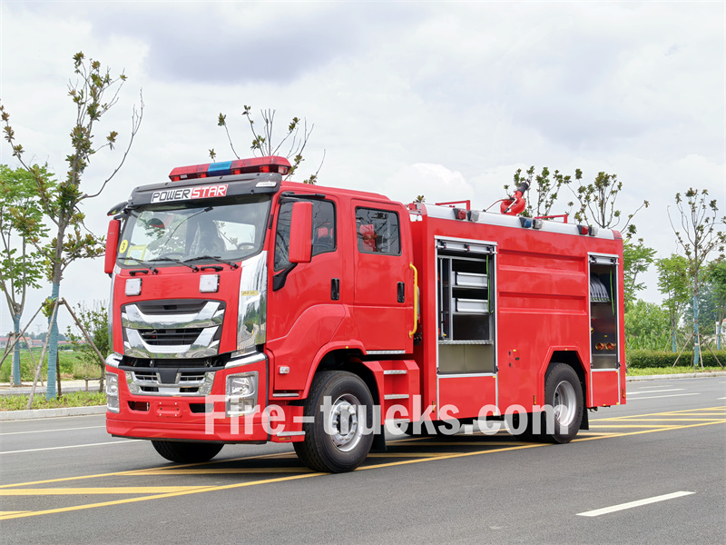
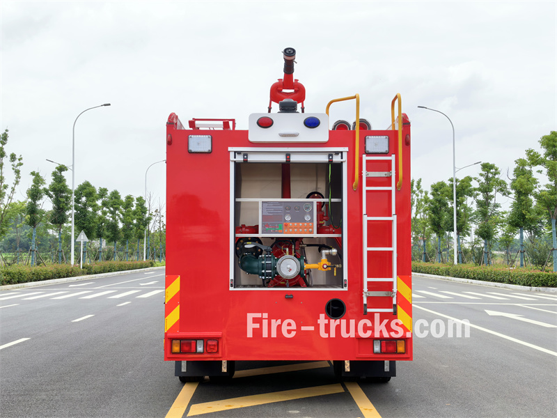
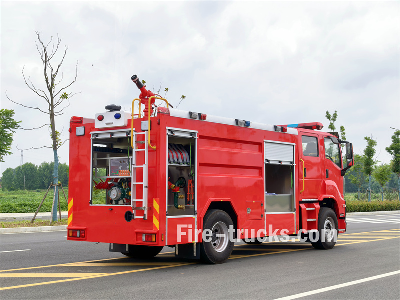
♦ Applicazione sul camion dei vigili del fuoco


Potresti essere interessato alle seguenti informazioni
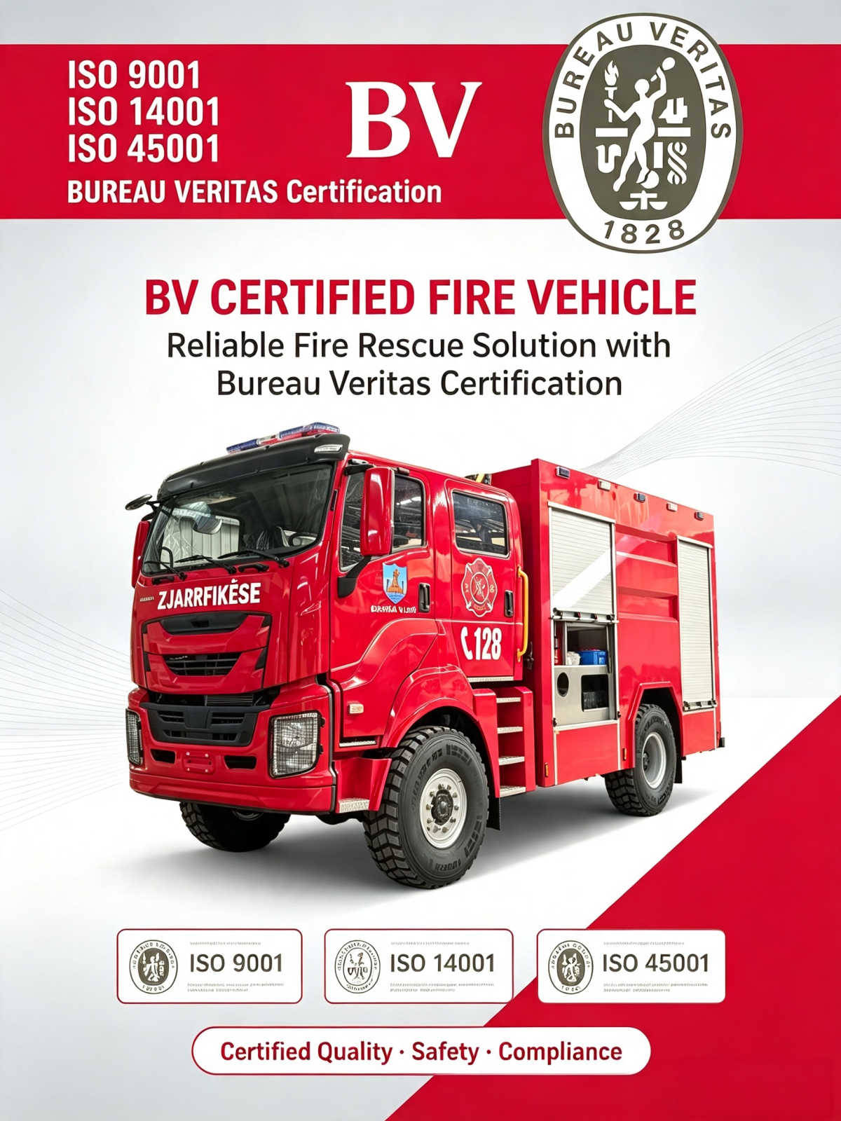
Che cos'è il certificato BV del rapporto sulle condizioni di ancoraggio dei camion antincendio GIGA ISUZU 4x4? 1. Definizione di base Si tratta di un rapporto scritto formale emesso da un'agenzia di ispezione marittima di terze parti (come BV, SGS, AIM Control, ecc.), utilizzato principalmente per i camion antincendio ISUZU GIGA, i veicoli per uso ingegneristico su navi Ro-Ro (Ro-Ro)** e il trasporto di merci generali. Contenuto principale: Il notaio pubblico ispeziona il posizionamento del veicolo nella stiva della nave, le catene/tenditori di ancoraggio, i cunei fermaruota e i punti di ancoraggio, confermando che la disposizione di ancoraggio è conforme alle "Procedure operative di sicurezza per lo stivaggio e il fissaggio del carico" IMO CSS e al "Manuale di fissaggio del carico" della nave. Download PDF: Rapporto sulle condizioni di ancoraggio con certificato BV dei camion antincendio GIGA ISUZU 4x4 2. Cosa include normalmente il rapporto (specificamente per la tua attività di esportazione di camion antincendio)? 1. Elenco dei veicoli, numero di telaio, posizione di carico 2. Metodo di fissaggio: numero di punti di ancoraggio, specifiche delle catene/tenditori, disposizione dei cunei fermaruota 3. Verifica dell'aspetto delle attrezzature di ancoraggio per danni o allentamenti 4. Controllo della distanza tra i veicoli e del centro di gravità 5. Foto sul posto (prove fondamentali) 6. Conclusione: L'ancoraggio è accettabile / Sono presenti difetti, è necessaria una correzione prima della partenza 3. Utilizzi principali nella tua attività di commercio estero (importante) 1. **Requisiti della compagnia di navigazione/del porto di destinazione**: Per alcune rotte verso Africa, Africa occidentale, Burkina Faso e Albania, al destinatario è richiesto di fornire questo rapporto come prerequisito per lo sdoganamento e l'accettazione del veicolo; 2. **Documento per la richiesta di risarcimento assicurativo**: Se il veicolo viene spostato o danneggiato in una collisione durante il trasporto marittimo, questo rapporto costituisce la base fondamentale per determinare la responsabilità: ✅ Ancoraggio accettabile prima della partenza → Il rischio tende a ricadere sulla compagnia di navigazione ❌ Ancoraggio inadeguato prima della partenza → Il proprietario della merce/lo spedizioniere si assume la responsabilità 3. **Evitare controversie tra acquirenti e venditori:** Dimostrare che il veicolo era fissato in modo sicuro secondo le specifiche al momento del carico, distinguendo tra "difetti di fabbrica" e "danni durante il trasporto marittimo". 4. Differenziazione dei termini simili (per evitare confusioni) 1. **Rapporto sulle condizioni del veicolo:** Un rapporto sulle condizioni esterne del veicolo (ispeziona graffi e condizioni generali prima del carico, ma non l'ancoraggio). 2. **Rapporto sulle condizioni di ancoraggio:** Un rapporto che ispeziona specificamente il processo di ancoraggio e fissaggio. 3. **Certificato di ancoraggio:** U...
Dettagli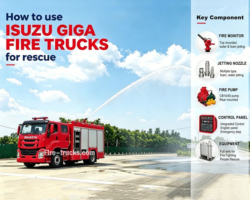
PesanteAutocarri antincendio schiumogeni ISUZU GIGA 5Xesportati nei paesi dell'Europa orientale, progettati sulla base del telaio dell'autocarro antincendio ISUZU GIGA 5X LHD 4x2, adottano lo stesso modello della nuova cabina ISUZU GIGA giapponese, sedile con sospensione pneumatica standard e aria condizionata per una guida confortevole. Il camion è dotato di motore diesel con tecnologia giapponese ISUZU modello 6HK1-TCG60, 221KW / 300HP e cilindrata di 7790ml, abbinato a un cambio manuale FAST a 9 marce, consumo di carburante molto ridotto, pneumatici anteriori standard 385/60R22.5 e posteriori 315/80R22.5, per un totale di 6+1 unità. I kit della sovrastruttura includono una cisterna acqua da 3000L basata su acciaio al carbonio e una cisterna schiuma da 500L realizzata in acciaio inossidabile #304, resistente per un servizio di lunga durata. Abbinato a una pompa antincendio CB10/40 super potente personalizzata con portata efficiente di 40L/s, abbinata a una doppia pompa antincendio sulla parte superiore del kit cisterna, con modello PL8/32 e portata efficiente di 32L/s.Automezzo antincendio di soccorso Isuzu GIGA 300HPabbinato a tutte le attrezzature antincendio necessarie, è un automezzo antincendio ideale per lo spegnimento degli incendi e il soccorso delle persone, ed è ampiamente utilizzato nel mercato dei paesi dell'Europa orientale. Servizio per Moldavia, Albania, ecc. EUROPA ORIENTALEAutocarro antincendio con cisterna schiuma ISUZU Fabbrica POWERSTAR TRUCKS è un produttore professionale nel settore degli autocarri,garantisce che tutti i prodotti siano nuovi di fabbrica e di alta qualità. Caratteristiche dell'autocarro antincendio ISUZU GIGA 5X: Nome Autocarro antincendio con pompa schiuma ISUZU GIGA da 3500L Cabina GIGA 5X, LHD / RHD personalizzato Verniciatura Rosso RAL3000 o modello R03 Motore 6HK1-TCG60 con 300HP e cilindrata 7790ml Trasmissione FAST a 9 marce Passo 4500mm Pneumatici Anteriore: 385/60R22.5 (2 pezzi) Posteriore: 315/80R22.5 (4 pezzi) Pneumatico di scorta: 385/60R22.5 (1 pezzo) Kit cisterna Pompa antincendio Cannone antincendio Avvolgitubo Attrezzi Cisterna acqua da 3000L Cisterna schiuma da 500L Pompa antincendio CB10/40, portata 40L/s Cannone antincendio PL8/32, portata 32L/s Avvolgitubo manuale da 50m con pistola Set completi come standard Come utilizzare l'automezzo antincendio ISUZU con cisterna schiuma: .
Dettagli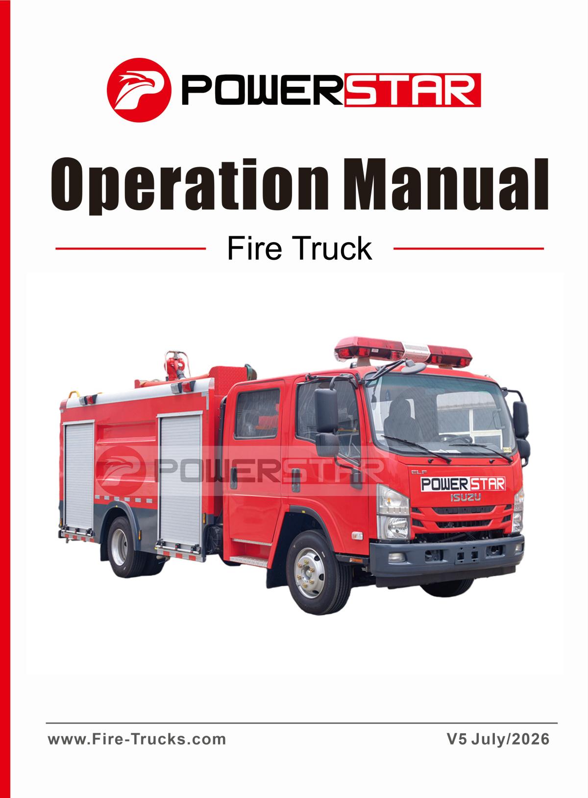
MANUALE DI SERVIZIO OPERATIVO AZIENDALE DEI CAMION ANTINCENDIO ISUZU NPR, chiamato anche ebook sulle operazioni dei camion antincendio ISUZU, manuale di addestramento dei veicoli antincendio ISUZU o manuale operativo aziendale dei camion antincendio e soccorso ISUZU. Il camion antincendio e soccorso ISUZU è compatto e maneggevole, adatto a diversi scenari di emergenza antincendio ed è un veicolo fondamentale per i vigili del fuoco professionisti locali e i parchi industriali. Dotato di serbatoi indipendenti per acqua e schiuma, può estinguere autonomamente gli incendi iniziali che coinvolgono materiali solidi come legno, tessuti e materiali da costruzione. Può inoltre miscelare liquido schiumogeno per gestire incendi di petrolio e liquidi infiammabili in depositi petroliferi, stazioni di servizio, piccoli impianti chimici e officine di riparazione auto. La schiuma isola l'ossigeno, riducendo rapidamente il rischio di riaccensione. Download PDF:MANUALE DI SERVIZIO OPERATIVO AZIENDALE DEI CAMION ANTINCENDIO ISUZU NPR Il VEICOLO ANTINCENDIO ISUZU, di piccole dimensioni e con un ridotto raggio di sterzata, può percorrere vicoli stretti nelle vecchie aree residenziali, strade cittadine, vie di servizio delle fabbriche e strade scolastiche, superando i limiti dei grandi camion antincendio e dando priorità alla soppressione degli incendi iniziali per prevenirne l'espansione. Può inoltre svolgere pattugliamenti antincendio di routine e ispezioni dei rischi presso aeroporti, banchine, parchi logistici e aree minerarie. Dotato di un set completo di tubi e strumenti di soccorso, può effettuare semplici operazioni di soccorso d'emergenza, evacuazione del personale e raffreddamento dopo incidenti stradali. Durante l'operazione, può estinguere autonomamente gli incendi e anche fornire acqua e schiuma ai grandi camion antincendio; è inoltre adatto per combattere piccoli incendi nelle foreste suburbane e per l'irrigazione e il raffreddamento nelle aree colpite dalla siccità. Dotato di un'illuminazione completa per le operazioni notturne, è adatto al servizio in qualsiasi condizione e viene ampiamente utilizzato nelle brigate antincendio comunali, nei parchi industriali, nelle stazioni di servizio, nei porti, nelle aree panoramiche e in altre unità, realizzando operazioni integrate di antincendio, pattugliamento e supporto d'emergenza. Video operativo aziendale del camion antincendio e soccorso ISUZU
Dettagli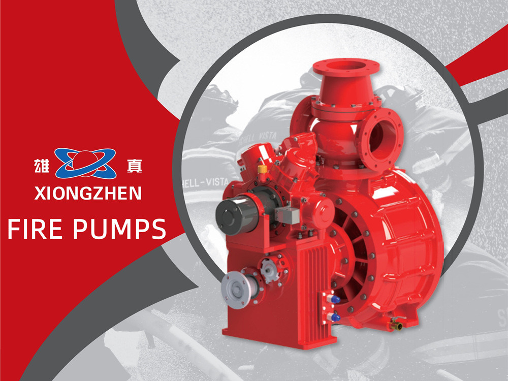
Per gli autocarri antincendio convenzionali, l'acqua è il mezzo principale per l'estinzione degli incendi e il soccorso. Come unità di potenza centrale dell'intero sistema di alimentazione idrica degli autocarri antincendio, la pompa antincendio montata sul veicolo determina direttamente l'efficienza di soppressione degli incendi, la pressione di alimentazione dell'acqua e la stabilità del funzionamento continuo del veicolo. Xiongzhen si occupa da molti anni della ricerca, sviluppo e produzione di pompe antincendio. Integrando strutture mature delle pompe nazionali e internazionali e nuovi materiali resistenti all'usura, abbiamo sviluppato una gamma completa di pompe antincendio montate sul veicolo a pressione medio-bassa e alta-bassa.Tutti i prodotti hanno superato la certificazione antincendio nazionale 3C e l'ispezione del tipo. Caratterizzati da erogazione stabile dell'acqua, adescamento rapido, struttura compatta e facile manutenzione, sono adatti per l'allestimento e il supporto di vari autocarri antincendio con serbatoio d'acqua, schiuma e soccorso d'emergenza. Pompe antincendio XiongzhenLe pompe antincendio Xiongzhen coprono una gamma completa di modelli: pompe a bassa pressione tra cui CB10/20, CB10/30, CB10/40, CB10/60, CB10/80, CB10/100, CB10/120 e CB10/140; pompe a pressione medio-bassa come CB20·10/15·30, CB20·10/20·40, CB20·10/30·60 e CB20·10/40·80; la pompa ad alta-bassa pressione CB40·10/7·50, oltre alle pompe a media pressione CB20/15, CB20/20 e CB20/30. Ogni modello è fornito con specifiche complete delle prestazioni, rapporti di trasmissione opzionali e dimensioni di installazione. In grado di soddisfare i requisiti di alimentazione idrica per l'allestimento degli autocarri antincendio e il soccorso d'emergenza sia a livello nazionale che internazionale, offrono prestazioni stabili, funzionamento semplice e manutenzione agevole. Le pompe antincendio della serie Xiongzhen sono principalmente assemblate con corpo pompa, bocchettone di riempimento dell'olio, tubo di ingresso dell'acqua, valvola di ritegno, dispositivo di adescamento a doppio pistone, ingranaggio di misurazione della velocità, riduttore e albero di ingresso. Le varianti a pressione medio-bassa sono inoltre dotate di valvole a sfera pneumatiche per la commutazione tra pressione media e bassa, valvole di ritegno a media pressione e valvole di ritegno a bassa pressione. L'unità utilizza un corpo pompa in alluminio pressofuso integrale per un'erogazione uniforme dell'acqua. Dotate di un meccanismo di adescamento a doppio pistone, le pompe a pressione medio-bassa offrono due modalità di azionamento tra cui scegliere: azionamento elettrico e azionamento tramite puleggia a cinghia, garantendo un adescamento rapido e un funzionamento intuitivo. Confronto dei parametri dei principali modelli di pompe antincendio Con diverse condizioni operative CB10/40 CB10/60 CB10/100 CB10/140 CB20·10/30·60 CB40·10/7.50 CB20/30 Portata(L/s) 40 60 100 140 60 30 30 28 42 70 9...
Dettagli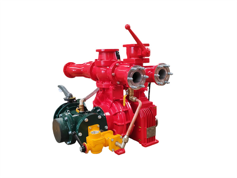
Il CB10/60-RS pompa antincendio montata su autocarro è composta da una pompa centrifuga monostadio a bassa pressione, una pompa del vuoto a doppio pistone, un dispositivo di disinnesto automatico della frizione elettromagnetica, un moltiplicatore di velocità, una tubazione di uscita con valvola di intercettazione e una tubazione di ingresso. ♦ Struttura principale e funzione (1) Pompa centrifuga monostadio a bassa pressione: Composta da un coperchio della pompa, corpo pompa, girante del primo stadio e albero della pompa, fornisce la pressione nominale e la portata nominale. (2) Moltiplicatore di velocità: Il moltiplicatore di velocità della pompa antincendio montata su veicolo CB10/60-RS ha un rapporto di aumento della velocità convenzionale di 1,440. (3) Pompa del vuoto a doppio pistone: Composta principalmente da un pistone, corpo pompa, albero della pompa e ruota eccentrica. La ruota eccentrica è dotata di un'asta guida del pistone e di una camicia in acciaio del corpo pompa. Le valvole di ingresso e uscita sono installate su entrambe le estremità della pompa a pistone. Quando la frizione elettromagnetica si innesta, la pompa a pistone inizia a funzionare. Durante il funzionamento, l'azione eccentrica della ruota eccentrica fa muovere alternativamente il pistone, espellendo gradualmente l'aria dalla pompa e dalla tubazione, migliorando così la qualità dell'aria. Si crea un vuoto all'interno della cavità per raggiungere lo scopo dell'aspirazione dell'acqua. 1. Valvola di intercettazione dell'uscita (4 pezzi); 2. Tubi dell'acqua di uscita sinistro e destro; 3. Raccordo di ritorno dell'acqua di raffreddamento del cambio; 4. Raccordo del manometro; 5. Valvola di ritegno dell'uscita; 6. Flangia del cannone ad acqua; 7. Pressostato dell'acqua; 8. Raccordo di ritorno dell'acqua in pressione di raffreddamento della presa di forza; 9. Flangia del serbatoio dell'acqua posteriore; 10. Valvola a sfera del serbatoio dell'acqua posteriore; 11. Cambio; 12. Frizione elettromagnetica e cablaggio; 13. Pompa di adescamento a pistone; 14. Raccordo del vacuometro; 15. Raccordo di adescamento del vuoto; 16. Interfaccia del tubo di ingresso; 17. Tubo a quattro vie di ingresso; 18. Valvola di scarico della pompa dell'acqua; 19. Tubo di ritorno dell'acqua in pressione di raffreddamento del cambio; 20. Tubo di ingresso dell'acqua in pressione di raffreddamento del cambio; 21. Valvola del livello dell'olio lubrificante del cambio; 22. Flangia di accoppiamento; 23. Cinghia di trasmissione; 24. Raccordo filettato dell'acqua in pressione del dosatore di schiuma (non disponibile sulle autocisterne dell'acqua); 25. Interfaccia del dosatore di schiuma; 26. Raccordo di uscita dell'acqua in pressione di raffreddamento della presa di forza; 27. Pompa antincendio per veicolo CB10/60; 28. Raccordo di uscita dell'acqua in pressione di raffreddamento del cambio; 29. Valvola a farfalla di ingresso posteriore (4) Tubazione di uscita dell'acqua a bassa pressione e valvola di in...
Dettagli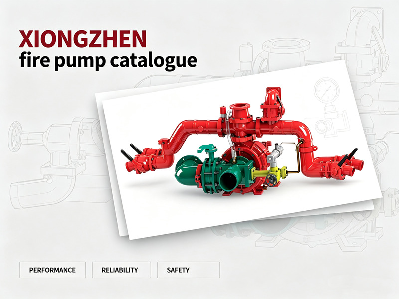
POWERSTAR è un produttore ed esportatore professionale di autocarri antincendio. La nostra gamma di prodotti comprende autocarri antincendio con serbatoio dell'acqua, autocarri antincendio a schiuma, autocarri antincendio a polvere secca e autocarri antincendio con scala aerea, ampiamente utilizzati nella lotta antincendio urbana, negli impianti petrolchimici, negli aeroporti e porti marittimi, nella protezione dagli incendi forestali e altro ancora. I nostri modelli di autocarri antincendio basati su telai ISUZU, HOWO e FAW sono esportati in molti paesi e regioni del Sud-est asiatico, Medio Oriente, Sud America e Africa. Dagli acquisti in grandi quantità da parte del governo filippino agli ordini ripetuti dei clienti nigeriani, POWERSTAR ha ottenuto una solida reputazione tra i clienti globali grazie alla qualità affidabile e ai servizi di personalizzazione professionale. Perché POWERSTAR sceglie le pompe antincendio XIONGZHEN?La pompa antincendio viene spesso chiamata il "cuore" di un autocarro antincendio: senza una pompa antincendio altamente efficiente e affidabile, un autocarro antincendio è semplicemente un veicolo per il trasporto di attrezzature e personale, incapace di svolgere realmente le missioni antincendio. Proprio per questo motivo, POWERSTAR applica gli standard più elevati nella selezione dei componenti principali.XIONGZHEN è un marchio noto nell'industria cinese delle pompe antincendio, con prodotti ampiamente utilizzati da molti produttori professionali di autocarri antincendio in tutto il paese. Basandosi su tecnologie avanzate provenienti da Germania, Austria, Stati Uniti e altri paesi, combinate con capacità indipendenti di ricerca e sviluppo, XIONGZHEN offre serie di pompe antincendio montate su veicoli le cui prestazioni competono con i prodotti importati. I principali vantaggi includono:• Prestazioni eccellenti e alta efficienza:Il design della girante centrifuga a due stadi e del corpo pompa con palette guida bilancia le forze radiali e assiali sull'albero della pompa, garantendo un funzionamento fluido ed efficiente.• Struttura compatta e funzionamento semplice:Il design integrato della camera delle palette guida e della camera di pressione rende la manutenzione e l'assistenza più pratiche.• Tecnologia innovativa di adescamento:Una pompa di adescamento elettrica a quattro pistoni con frizione elettromagnetica offre una maggiore capacità di aspirazione dell'acqua e prestazioni di aspirazione superiori rispetto alle tradizionali pompe a due pistoni, prevenendo efficacemente i danni causati dal funzionamento a secco delle tenute meccaniche in condizioni senza acqua.• Certificazione autorevole:L'intera linea di prodotti ha superato i test di tipo del Centro nazionale di supervisione e ispezione della qualità delle attrezzature antincendio e soddisfa lo standard GB6245-2006. POWERSTAR sceglie le pompe antincendio XIONGZHEN proprio grazie alla loro qualità affidabile e alla tecnologia comprovata, garantendo che ogni auto...
Dettagli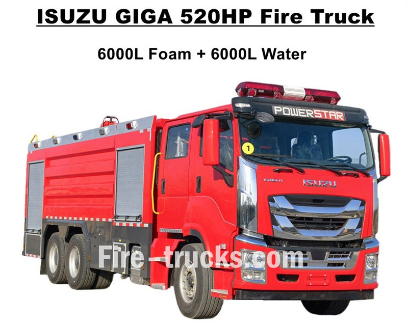
Qualità superioreAutocarri antincendio ISUZU GIGAesportati in Africa occidentale, Burkina Faso, progettati sulla base del telaio per autocarro pesante ISUZU GIGA VC66 6x4, adottano la nuova cabina GIGA VC66, sedile con sospensione pneumatica standard e aria condizionata per una guida confortevole. L'autocarro è dotato di motore diesel con tecnologia giapponese ISUZU modello 6WG1-TCG62, 520HP e cilindrata di 15681cc, abbinato a un cambio manuale FAST a 12 marce, con consumo di carburante molto ridotto, pneumatici anteriori standard 385/80R22.5 e posteriori 315/80R22.5, per un totale di 10+1 unità. I kit della sovrastruttura includono una cisterna d'acqua da 6000L e una cisterna schiumogeno da 6000L, entrambi realizzati in acciaio inossidabile #304, durevoli per un servizio di lunga durata. Abbinati a una potente pompa antincendio CB10/140 personalizzata con portata efficiente di 140L/s, con doppia pompa antincendio montata sulla parte superiore del kit cisterna, modello PL8/64 e portata efficiente di 64L/s.Autopompa antincendio ISUZU GIGA 520HPabbinata a tutte le attrezzature antincendio necessarie, è un'autopompa ideale per lo spegnimento degli incendi e il soccorso delle persone, ed è ampiamente utilizzata nel mercato del Burkina Faso. Autocarro antincendio ISUZU GIGA 520HP con cisterna schiumogeno da 14.000L fabbrica CS TRUCKS è un produttore professionale nel settore degli autocarri,garantisce che tutti i prodotti siano nuovi di fabbrica e di alta qualità. Caratteristiche dell'autocarro antincendio ISUZU: Nome Autopompa antincendio ISUZU GIGA con cisterna schiumogeno da 12000L Cabina GIGA VC66 Motore 6WG1-TCG62 con 520HP e cilindrata di 15681cc Trasmissione FAST a 12 marce Passo 4600+1370mm Pneumatici Anteriore: 385/80R22.5 (2 pezzi) Posteriore: 315/80R22.5 (8 pezzi) Cisterna Cisterna schiumogeno da 6000L (Acciaio inossidabile #304) Cisterna acqua da 6000L (Acciaio inossidabile #304) Pompa antincendio CB10/140 con portata di 140L/s Monitor antincendio Anteriore: PL8/64 con portata di 64L/s Posteriore: PL8/64 con portata di 64L/s Attrezzatura Set completo di attrezzature antincendio personalizzate Come utilizzare l'autopompa antincendio ISUZU con cisterna schiumogeno: .
Dettagli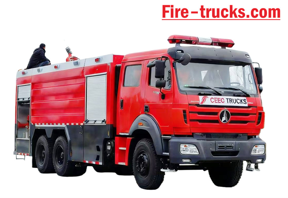
Beiben Autopompa basata sul telaio Beiben 2638 tipo II modello 6*4 con guida a sinistra, carrozzeria la capacità potrebbe arrivare fino a 12.000 litri, inclusi 10.000 litri di cisterna per l'acqua e 2.000 litri di serbatoio per la schiuma, Beiben 2638 soccorso antincendio camion dotato di pompa antincendio XIONGZHEN CB10/60 e monitor antincendio PL8/48, molto comodo per Uso quotidiano. Utilizzato principalmente per progetti antincendio in qualsiasi area in cui sia necessario. Il veicolo progettato per sfruttare appieno i vantaggi del telaio originale del camion del marchio Beiben, considerare appieno la praticità e l'affidabilità del prodotto, nonché il telaio di nuova concezione. Il corpo il materiale è acciaio al carbonio standard internazionale con verniciatura anticorrosione e acciaio inossidabile, che può essere efficace per evitare la ruggine e garantire una lunga durata. L'autopompa Beiben 6x4 è dotata di presa di forza Sandwich, pompa antincendio, monitor antincendio, sala equipaggio, tubo flessibile scatola, sala pompe, autocisterna per polvere secca e sistema di azoto, abbinato ad avvolgitubo per condotte, inglese scatola di controllo della versione, tubazione di ingresso e uscita, scala di salita posteriore, lampada a cuscino superiore e tutto il necessario attrezzature antincendio. Cabina a doppia fila personalizzata con 2+4 posti, piacevole sensazione di guida. Pertanto, IL Questo veicolo è un'autopompa ideale soprattutto per i progetti di spegnimento incendi. [if gte mso 9]> Normale 0 7,8 磅 0 2 false false false EN-US ZH-CN X-NONE
Dettagli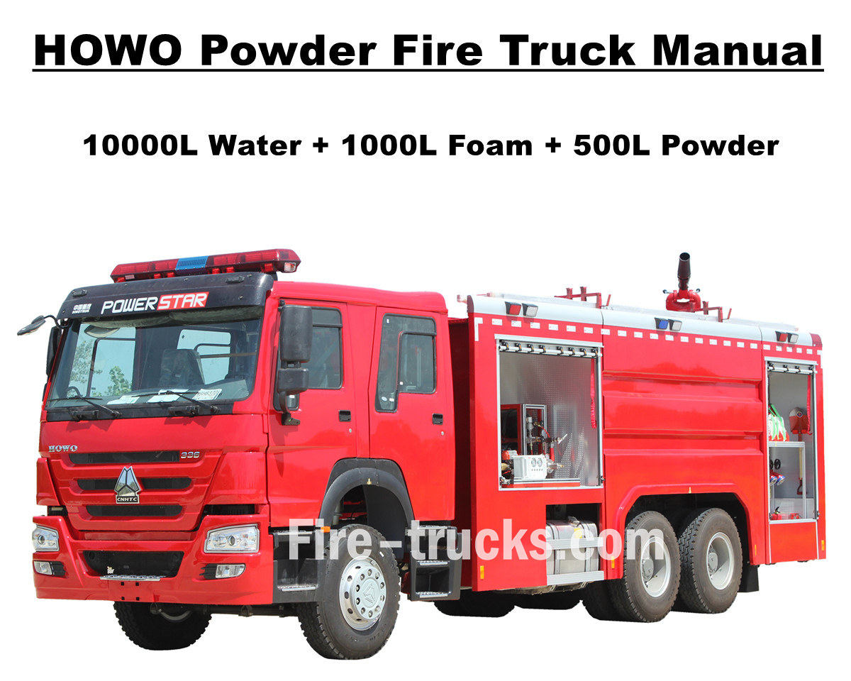
Il cliente Africa Mauritania ha acquistato in totale 4 unità Autopompa antincendio Sinotruk Howo Da POWERSTAR TRUCKS e utilizzato nella capitale Nouakchott. Il camion dei pompieri, noto anche come autopompa o autopompa, è un veicolo progettato e prodotto per soddisfare le esigenze di molteplici progetti di spegnimento incendi e soccorso a livello internazionale. Doppia fila di cabine personalizzate per il trasporto dei vigili del fuoco, varie attrezzature e strumenti antincendio per la lotta antincendio, il soccorso antincendio, ecc. Per garantire che i camion dei pompieri HOWO lavorino in modo più efficiente, abbiamo personalizzato il camion per equipaggiarlo con scale in lega di alluminio, schiumogeno e agente antincendio a polvere secca e cisterne di stoccaggio, pompa antincendio efficiente modello CB10/60 abbinata al monitor antincendio PL8/48 e portata di spruzzo di oltre 70 m, naspi antincendio con pistola per lo spegnimento di incendi a lunga distanza, autorespiratore con maschera, indumenti protettivi, strumenti di soccorso, kit di pronto soccorso, ecc. Tutti i servizi per i camion dei pompieri HOWO garantiscono un lavoro efficiente e affidabile. Per garantire ai clienti della Mauritania un utilizzo più semplice ed efficiente dei camion antincendio HOWO, tutti i camion sono dotati di un catalogo completo in lingua inglese per l'assistenza, che comprende il manuale utente per la guida al funzionamento, il manuale del camion e il manuale dei pezzi di ricambio per l'uso e la manutenzione. Autopompa antincendio SINOTRUK HOWO da 14.000 litri Fabbrica POWERSTAR è un produttore professionale nel settore dei camion, garantiamo che tutti i prodotti sono nuovi di zecca e di alta qualità. » Ⅰ. Vantaggi del camion dei pompieri HOWO: ★ Potente motore diesel WEICHAI da 247KW / 336HP, 100.000 Km senza problemi. ★ Cabina classica SINOTRUK HOWO HW76, design europeo ★ Pompa antincendio CB10/60 montata, portata 60 L/s, super affidabile ★ Cannone antincendio ad acqua PL8/48 montato in alto, servizio durevole ★ Bombola di polvere secca da 500 litri con azoto, con valvole di controllo dell'aria ★ Sistema di controllo integrato per schiuma e polvere, con pannello posteriore » Ⅱ . Disegno del camion dei pompieri Howo Rescue: [if gte mso 9]> Normale 0 7,8 punti 0 2 false false false EN-US ZH-CN AR-SA /* Style Definitions */ table.MsoNormalTable {mso-style-name:普通表格; mso-tstyle-rowband-size:0; mso-tstyle-colband-size:0; mso-style-noshow:yes; mso-style-priority:99; mso-style-parent:""; mso-padding-alt:0cm 5.4pt 0cm 5.4pt; mso-para-margin:0cm; mso-pagination:widow-orphan; font-size:10.0pt; font-family:"Calibri",sans-serif; mso-bidi-font-family:"Times New Roman";} To guarantee Mauritania Nouakchott clients purchased satisfy HOWO 6x4 Water & Foam & Powder Fire Truck, so we POWERSTAR Engineer Department do design the truck firstly, then start for production. Howo fire truck equipped with Sandwich PTO, fire pump, fire monitor, crew room, hose box, pump room, English ver...
Dettagli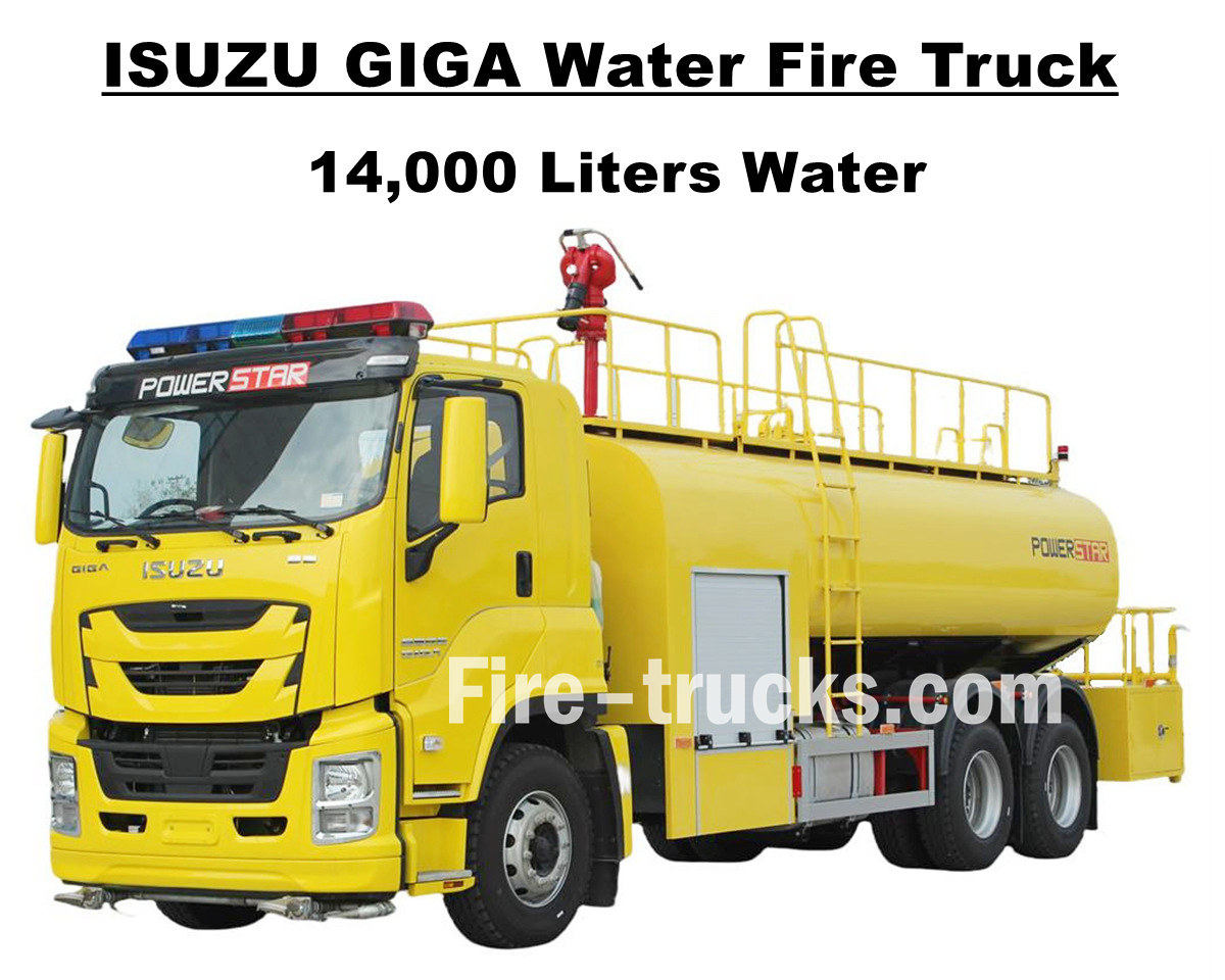
Cliente sudamericano Sig. Joseph dall'Hondura, che ha acquistato 1 unità Camion antincendio Isuzu GIGA VC66 14000L 3700 galloni d'acqua da POWERSTAR TRUCKS, Progettato sulla base del telaio del camion pesante giapponese ISUZU GIGA 6x4, equipaggiato con motore diesel modello 6UZ1-TCG60 con potenza di 280 kW / 380 CV, un motore a 6 cilindri, 4 tempi, raffreddato ad acqua, turbocompresso e intercooler, cilindrata efficiente di 9839 ml, abbinato al cambio manuale FAST a 12 marce standard internazionale, 12 marce avanti e 2 marce indietro, riduce efficacemente il consumo di carburante, 13 unità di pneumatici in acciaio installati con modello 12R22.5, inclusa una ruota di scorta, molto adatto a diversi tipi di condizioni stradali e adatto per l'arrampicata in montagna. Il passo può essere multiplo opzionale con 4600 + 1370 mm. servizio progettato in modo pratico e adatto per progetti di estinzione incendi in più aree. L'autocisterna antincendio Isuzu GIGA da 3700 galloni si basa interamente sulla tecnologia giapponese del telaio del camion ISUZU, con cabina GIGA VC66 originale dotata di aria condizionata con funzione di riscaldamento e raffreddamento per una guida confortevole. Il camion è dotato di un cassone cisterna per l'acqua interamente in acciaio inossidabile SS304, con un volume efficiente di 14000 litri, pari a 3700 galloni, equipaggiato con una pompa antincendio CB10/60 di marca cinese e un monitor antincendio PS8/50 sulla parte superiore del cassone, set completi di attrezzature antincendio e verniciatura personalizzata giallo limone per l'intero camion, il che rende il camion un veicolo ideale per progetti di spegnimento incendi nelle strade e nelle comunità dell'Honduras. Il camion è inoltre dotato di un catalogo completo in inglese per l'assistenza, che include il manuale utente per la guida operativa, il manuale del camion per l'utilizzo del camion GIGA e il manuale dei pezzi di ricambio per la manutenzione. Autopompa antincendio Isuzu GIGA da 14.000 litri Fabbrica POWERSTAR è un produttore professionale nel settore dei camion, garantiamo che tutti i prodotti sono nuovi di zecca e di alta qualità. » Ⅰ. Vantaggi del camion antincendio ad acqua Isuzu: ★ Potente motore diesel 6WG1 da 280KW / 380HP, 100.000 Km senza problemi. ★ ISUZU VC66 nuova cabina GIGA, design europeo ★ Pompa antincendio CB10/60 montata, portata 60 L/s, super affidabile ★ Cannone ad acqua PS8/50 montato in alto, servizio durevole ★ Sistema di controllo integrato, con pannello laterale ★ Dipinto personalizzato giallo limone, brillante e bellissimo Pompa antincendio CB10/60 Modello : CB10/60 Pressione : 1,0 MPa Pressione massima di esercizio : 1,232 MPa Portata : 60L/s a 1,0Mpa, velocità 3286±50r/min, potenza 102kW, profondità di aspirazione 3m 42L/s a 1,3Mpa, velocità 3519±50r/min, potenza 106kW, profondità di aspirazione 3m 30L/s a 1,0Mpa, velocità 3120±50r/min, potenza 73kW, profondità di aspirazione 7m Rapporto di velocità : 1:1.44 Monitor antincendio PS8/50 Modello : ...
Dettagli
Per favore, continua a leggere, resta aggiornato, iscriviti e saremo lieti di conoscere la tua opinione.

 Rete IPv6 supportata

 italiano
 English
 français
 Deutsch
 русский
 español
 português
 Nederlands
 العربية
 日本語
日本語 한국의
한국의 Türkçe
 Melayu
 ไทย
ไทย Tiếng Việt
 Indonesia
  中文
中文 қазақ
қазақ Filipino
 မြန်မာ
 српски